Ship Aft End Vibration – A report writing
This article is furnished as a report writing to your superindent on Aft end vibration and Suggested remedies, From Second engineer
Date: -DD.MM.YY
Technical Superintendent
XYZ Shipping Let
Germany,
Sub: Aft end vibration and Suggested remedies, From Second engineer M.T. XXXXX XXX
Ref: – Your letter dated on – DD.MM.YYYY
Dear Sir,
This is in connection with the mentioned letter regarding the “Severe aft end Vibration” Now let me furnish the related observations, findings and possible remedies for your kind perusal and our future course of action.
INVESTIGATION:
1. Engine performance has been taken. Load found to be equally distributed among all the cylinders i.e. there is no power imbalance
2. Crank shaft deflection has been taken all units crankshaft deflection readings are within the maker’s specified values
3. Engine all units main, crankpin and cross head bearing and also thrust bearing clearance taken and found within normal limit.
4. Main Engine all parameters are within limit.
5. Work done History of engine is checked to find out any history of overloading, scavenge fire etc.
6. Engine foundation bolts, fie-rod tightening torque all are in proper order.
7. Engine top bracing attachment to the ship’s hull has been checked.
1. Any loose fitting of the rotating and reciprocating masses inside the cylinder has been checked and found none.
2. Under water hull and propeller Inspecting carried out and apparently no damage was observed to the propeller blade.
3. This vibration is question has been experienced at the aft end at the service speed when running in deep draught.
After the investigation I have concluded the below mentioned causes for the problem
Causes:-
1. The propeller Tip clearances b/w The blade tip and the hull might have reduced due to the shifting of propeller it will cause severe pressure pluses into the hull which will cause vibration
if Tip clearance reduces the more vibration. Tip clearance formula = 0.48 – 0.2Nb
Here Nb is the number of blades. In 4 bladed Propeller min clearance = 0.48 – 0.02 X 4 = 0.40m = 400 mm
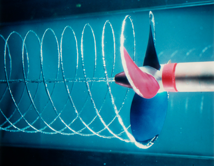
- High pitch noise originates from propeller transmitted vibration which is called “Singing of propeller”. This is caused due to elastic vibration
- Propeller induced vibration and hull induced vibration may come in phase due to the main engine units enacting to the TDC position and propeller blade entering into the wake.
- Conventional propeller induces more vibration that skewed propeller as conventional propeller has variable wake around the propeller.
- Positioning of the propeller is not correct
- Propeller rake is less.
- Propeller is not dynamically balanced at the service speed.
Possible remedies:-
1) Trim the astern side of the vessel by filling aft peak tank to reduce cavitation of propeller and there by noise and vibration
2) The no of blades of the propeller and the number of units of the main engine should be different. So, change the propeller number from even number i.e. in question from (4) to add no (5) for better dynamic balancing.
3) After measuring the “propeller draw” i.e. the distance from the front side of the boss to the starting point of tapper on the shaft which is not cornered by the boss – if found incorrect then re-bedding and re-positioning of the boss to be carried out.
4) Highly skewed propeller blade to be used so that each blade has areas in different wake region simultaneously so that large variation of thrust and torque do not occur as it rotates. This refers to softer interaction.
5) Some flow correction devices like ducts, vanes, roofs etc to improve flow distribution into propeller
6) Main engine should not be run continuously in the barred speed range
7) Vibration can be reduced by electric driven moment compensator in the steering gear room without going for any other modification
8) Slightly increase more blade area by over lapping the blades.
9) Propeller rake to be increased by changing the propeller so as keeping the diameter same but increasing the TIP CLEARANCE.
10) When propeller is fitted, take M/E no#1 unit on TDC, there is a marking on the propeller boss which need to be in alignment with the marking on the tail shaft. This done to prevent resonance condition.
Your faithfully
ABC, 2/E, M/T Ship Name