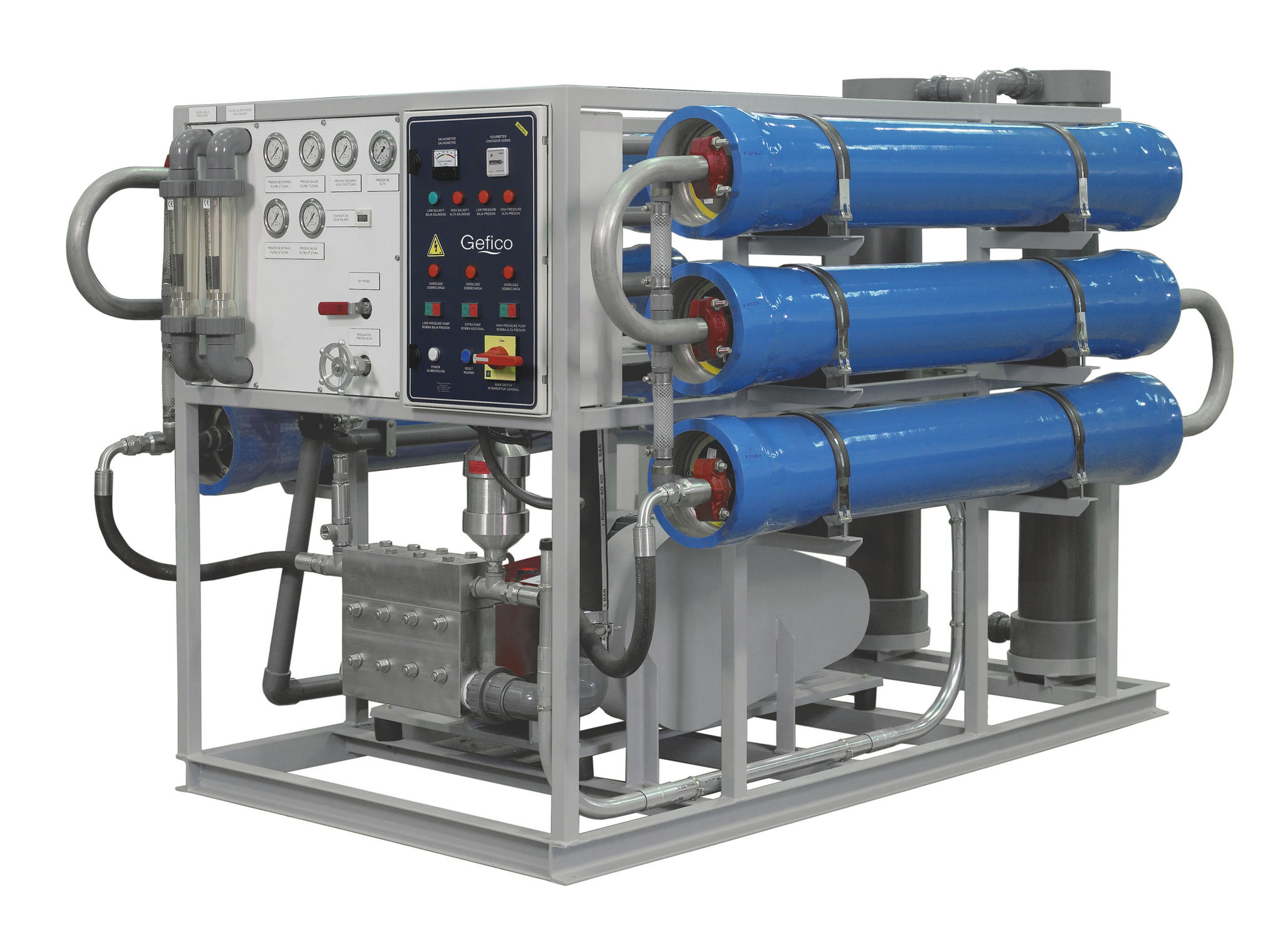
Marine shipboard Reverse Osmosis system
Reverse Osmosis
- To understand Marine shipboard Reverse Osmosis system and its functioning we should first attend to few basic things. Reverse osmosis is one of the most desalination processes that is used widely on most ships and also for household water production. RO plant is considered one of the most successful method of desalination as the size of the system can be reduced or increased to suit the requirement varying from a house hold process to an industrial process with larger output.
Let us first understand what is Osmosis?

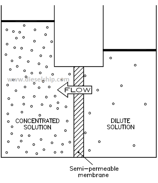
- Osmosis is a natural process involving fluid flow across a membrane which is a semi permeable one. The direction and relative quantities of fluid flow is determined by the chemical potential which is a function of pressure, temperature and concentration of dissolved solids.
- When two solutions of different concentrations are separated by a semi permeable membrane, water from the less concentrated solution will, due to the natural phenomenon of osmosis, pass through the membrane to dilute the more concentrated solution to make it an equivalent concentration to itself.
In simple words: If a container separated in to two by a semi-permeable membrane is filled with fresh water one side and sea water on the other side, the fresh water will diffuse through the membrane and move towards sea water side to equal the concentrations on both the sides.
Osmotic Pressure:
- This is one of the important factors in Osmosis & Reverse Osmosis process. if the hydraulics of this process are taken into account, as the water passes from the less concentrated solutions into the more concentrated solution to dilute it, the static head of the more concentrated solution increases and the one of the less concentrated solution decreases thus giving a net pressure.
- Equilibrium of the two solutions occurs when the pressure differential is sufficiently high to stop the fluid flow across the membrane – this pressure is called the osmotic pressure.
Reverse Osmosis
We have seen what Osmosis is! Now, what is Reverse Osmosis?
- Reverse Osmosis is the use of this natural process in the reverse direction. Pressure is exerted on the more concentrated side of the membrane to overcome the natural osmotic pressure and force water ‘out of’ the concentrated solution and through the membrane.
- Particles, bacteria and the larger organics are blocked by molecular filtering, however RO also involves an Ionic repulsion process, where by only water is allowed to pass through the semipermeable membrane, whilst virtually all dissolved molecules are rejected. The semipermeable membrane rejects multi charged ions such as calcium and sulphate at rates exceeding 99% while single charged ions such as sodium are rejected at rates from 90-96%.
Permeate??
- In Marine shipboard Reverse Osmosis system the fresh water produced through such membranes is called Permeate. According USPH (United States Public Health Service) rules and regulations, such water until treated with required PPM of Chlorine and pH correction made to maintain the pH value not more than 7.8 may not be called as potable water; hence it’s called a ‘Permeate’.
Reverse Osmosis process flow chart.
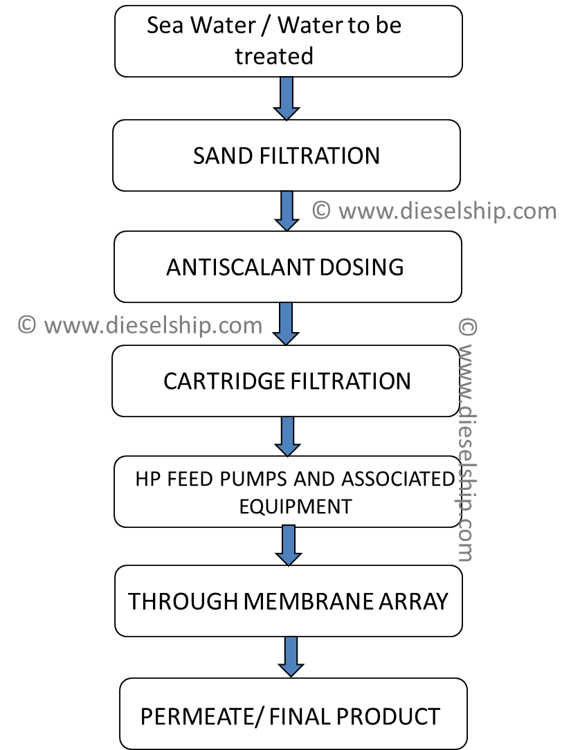
Flowchart Description
Now let us get deeper into each process charted down in the flow chart.
1. Feed Water:
- This is typically the water that needs to be desalinated. Feed water is supplied to the system using a feed pump. Feed is passed through a strainer. The same pump is used to back wash the Sand filters which we will see in next steps.
- For a shipboard environment it is the sea water. But remember, RO plant can only be operated outside 4 nautical mile limits to avoid shore based contamination in waters close to the shore line.
2. Sand Filtration:
- This process is for the removal of relatively large suspended solids that may be present in the raw feed water. Sand filtration is carried out by a filter vessels (Usually 2 in numbers or more depending upon quality of feed water) which typically contains a combination of different dimension grits stored in layers with coarse sand.
- Empty space is intentionally left above the grit media to allow space for bed expansion during filter back washing. The design throughput of the filter is such that they will provide sufficient filtered water for correct operation of the RO Plant. The total design flow rate of filters in parallel is set to a required value, this flow should not be exceeded as the filtration rate for optimum performance will be exceeded which in turn could mean a vastly reduced quality filtrate.
Alright, i have mentioned the word back-washing twice above, so let us see what back-washing is before proceed to the next steps of RO filtration.
- Back-washing of the filters is carried out to remove the accumulated solid particulates from the filtering media layers; it involves reversing the normal flow and discharging it to waste. Basically, the sand filter accumulates all debris collected on the bottom ( flow through sand filter is from the bottom to top), if the same is not removed then the filtering capacity of the same will be reduced. To remove such impurities collected , the RO system is put on stand-by mode and fresh water is forced in opposite direction into these filters which washes the debris out. This water is discharged overboard.
- Back-washing is carried out on a set frequency depending upon the feed quality or if the differential pressure increases by 1.0 bar between the inlet to the outlet.
- The backwash flow rate will vary depending upon the feed water temperature. It is critical that the correct flow rate is used; a satisfactory wash may not be achieved if it is too low or, on the other hand, media may be washed away if the wash water flow rate is too high.
Lets us get back to our flow chart. The next step is the Anti-scalant Dosing!
3. Anti-scalant dosing
Antiscalants are a family of chemicals designed to inhibit the formation and precipitation of crystallized mineral salts that form scale. Most antiscalants are proprietary organic man-made polymers (e.g. polyacrylic acids, carboxylic acids, polymaleic acids, organo-phosphates, polyphosphates, phosphonates, anionic polymers, etc.). The molecular weight of these polymers can range from 2,000 to 10,000 Dalton.
- Seawater contains sparingly soluble salts of Calcium, Barium, etc. These salts naturally have no tendency to precipitate, however, as the seawater passes through the plant and permeate is removed, the concentration of salts increases to such a degree that precipitation on the membrane surface can occur and thereby reduce their performance.
- To suppress the precipitation of these salts a solution of a proprietary antiscalant compound is dosed into the feed water which acts as a scaling inhibitor, thus allowing more efficient operation.
IF YOU ARE INTERESTED TO READ MORE ABOUT ANTISCALANTS AND DISPERSANTS USED IN RO PLANT Antiscalants and Dispersants used in RO plants PLEASE NOTE THIS PUBLICATION BELONGS TO ITS AUTHOR, DIESELSHIP DOESNT HAVE ANY COPYRIGHTS ON THE ATTACHED FILE.
4. Cartridge Filtration
- The feed water free from large suspended solids and dosed with antiscalant is passed through a 10 micron absolute rated cartridge filter, this ensures that the feed water to the RO membrane elements is free from any fine particulate matter ensuring maximum performance from the RO membrane elements, the filter also protects the high pressure pump in the event of a sand filter lateral failure.
5. High pressure feed Pumps
- The next step is feeding the membranes, high pressure feed Pumps aid this operation. As RO process involves pressure exerted on the fluid with the higher concentration to overcome the ‘Osmotic Pressure’ these pumps develop such high pressure depending on the pressure rating of the membranes.
- The high pressure pump supplies the pressure needed to push water through the membrane, even as the membrane rejects the passage of salt through it.
Typical pressures used in marine shipboard Reverse Osmosis system
- For brackish water range from 225 to 375 psi (15.5 to 26 bar, or 1.6 to 2.6 MPa).
- For seawater, pressure range from 800 to 1,180 psi (55 to 81.5 bar or 6 to 8 MPa).
Such high pressure is achieved by one or more HP pumps running in parallel. Usually these are axial piston pump.
Energy Recovery Unit

ENERGY RECOVERY
The energy recovery device recovers hydraulic energy from the high pressure reject stream and transfers that energy to the feed stream. In real terms, for example, the high pressure pumps would only need to delivery 16.75 m³/h at 59.5 bar instead of 16.75 m³/h at 74 bar.
In my 10 years of experience with energy recovery devices, It is really unfortunate that, i couldn’t find a manufacturer around the word who could produce good quality recovery device. These devices fail atleast once a year and the cost of a new device is close to USD 6000 and replacement is the only option as repairing it costs more than a new unit. After we compared the fuel savings due these recovery unit is much lower than USD 6K. Therefore, we simply by-pass them.
Next step & Final step is MEMBRANE ARRAY;
Semi-Permeable membrane stack usually used on RO plants.
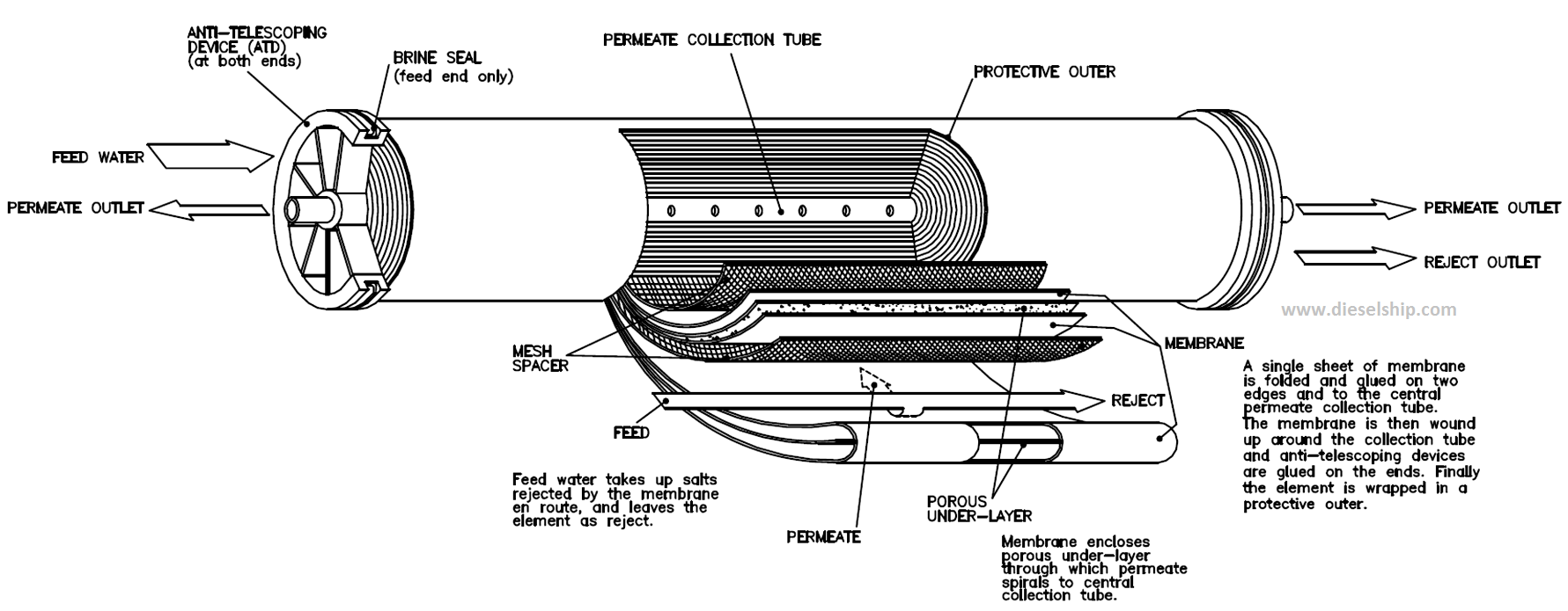
- Filtered, pressurized water is passed to the RO membrane elements and is desalinated. Within each stream, feed water enters the first vessel and is split into two flows, permeate (high quality, potable water) and reject (concentrated feed water). The reject from the first vessel then feeds the second vessel where again it is split into two flows, permeate and reject. This process is the same in each of the remaining streams.
- Here you should understand what a vessel and stream mean. Few vessels join together to make a stream. 3 or more vessels are connected and enclosed into a container which is called a stream.
- Reject from the last vessel in each of the three streams is manifolded together then flows through the reject control valve and to waste. The reject control valve is used to regulate the pressure within the membrane stack, which in turn regulates the permeate flow rate and quality.
I have tried my best to give you maximum information i have learnt through my different levels of shipboard experience on Marine shipboard Reverse Osmosis system i may have missed things. Please feel free to post your comments below. Thank you.