Fatigue of engineering components
* Fatigue is the progressive and localized structural damage that occurs when a material is subjected to cyclic loading. The nominal maximum stress values are less than the ultimate tensile stress limit, and may be below the yield stress limit of the material.
* Fatigue occurs when a material is subjected to repeated loading and unloading. If the loads are above a certain threshold, microscopic cracks will begin to form, eventually a crack will reach a critical size, and the structure will suddenly fracture. The shape of the structure will significantly affect the fatigue life; square holes or sharp corners will lead to elevated local stresses where fatigue cracks can initiate. Round holes and smooth transitions or fillets are therefore important to increase the fatigue strength of the structure.
Low stress high frequency

– Low stress-high frequency curve, typical of vibration induced stress.
High stress Low frequency

– High stress- low frequency curve. Typical of an air vessel being topped up automatically.
S-N curve
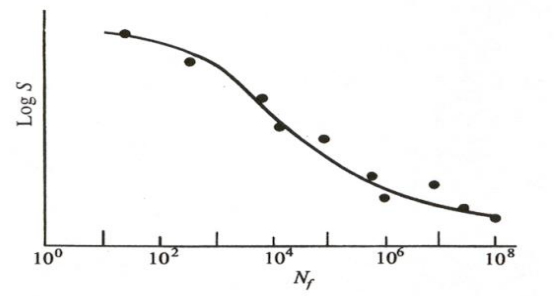
* In high-cycle fatigue situations, materials performance is commonly characterized by an S-N curve, also known as a Wohler curve. This is a graph of the magnitude of a cyclic stress (S) against the logarithmic scale of cycles to failure (N).
* Materials can be tested to find the relationship between the applied stress and the number of stress cycles. These tests produce the characteristic S-N curves as reproduced below, and attempt to define the number of cycles to failure for the two variables of S and N.
* It can be seen that if the level of stress increases, then the time to failure is reduced, and the component will fail earlier. Similarly if the component is operated for too many cycles, then it will also fail at the normal level of applied stress.
The influence of material defects on the safe operating life of engineering component.
– Surface roughness, porosity or foreign inclusion (Slug, oxides) abrupt change in section due to manufacturing defects causes severe stress raisers and reduce fatigue strength.
– Coarse grain, chemical composition and cold working causes residual stress to remain in the material and reduces the fatigue strength of material.
– Corrosion environment, erosion during service and decarbonisation during processing or heat treatment reduces fatigue strength.
– When a material defect occurs, then the level of stress in a localized area around that defect will rise. The level of the stress increase will be dictated by the position of the crack, its orientation to the applied stress, and the level of applied stress in the material. Normally any material defect, which increases the stress level, will cause the component to fail at an earlier stage.
Factors which influence the possibility of fatigue cracking of a bed plate transverse girder
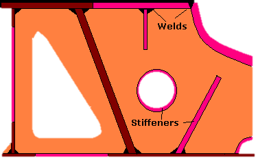
* The bedplate acts as the main strength member, maintains correct alignment and supports the weight of the components. It must be capable of withstanding the fluctuating forces created during operation and transmit them to the ships structure. In addition it may also collect lubricating oil. In slow speed engine design, it consists of a deep longitudinal box section with stiffening in the form of members and webs.
* Transverse members are fitted between each throw of the crankshaft. These support the main bearing saddles and Tie-rod connection. They are attached to the structure by substantial butt welds. To reduce the engine height the sump of the bedplate may be sunken allowing it to be fitted into a recess in the ships structure.
Loads & Stresses on a bedplate:
– The firing load (Gas pressure) acting downwards and tie-rod stresses acting upwards.
– Primary and secondary forces and external movements due to rotating and reciprocating masses.
– H-type and X-type guide force movement
– Axial vibration due to in-place bending of crankshaft.
– Torsional stress due to varying torque and propeller thrust.
Causes of fatigue cracking:
– Cylinder overload due to excess power.
– Incorrect crankshaft alignment.
– Manufacturing fault like Small material defect, High residual stress in weld joints, Hardening of heat affected zone, presence of dissolved oxygen.
– Tank top deformation due to pressurization of double bottom tank top or over heating of tank fluid.
How the risk of such cracking can be minimized
– Bed plate parts are made from mild steel pates and steel castings which are assembled and welded together so that the bed plate is strong longitudinally and transversely with good resistance to twisting along its length.
– The longitudinal strength is obtained by making each side of the bedplate in the form of a box girder formed with 2 flanges and 2 webs.
– The cast steel cross girders in which the main bearings are placed contributes the bedplate its transverse strength and resistance against twisting along its length.
– Apart from the above, resin cast chocks are used between bedplate and double bottom tank top to absorb the shocks and cycle stresses which are almost twice as efficient compared to conventional cast chocks.
To minimize these effects the following routine checks should be carried out:
* Monthly checks of engine load using power cards, and measuring the cylinder peak pressures using peak pressure indicators or power cards
* Yearly checks of the tie bolt tension
* Yearly checks of the tension of the main bearing jack bolts
* Three monthly checks of crankshaft alignment.
By preventing an increase the applied stress on the girder, the likelihood of cracking is greatly reduced, however regular visual checks should also be carried out beneath the main bearing.