ROTARY VANE STEERING GEAR
– Rotary vane steering gear is usually fitted with 3 fixed vanes and 3 moving vanes and can turn to 700 of total rudder movement i.e 350 on each side.
– Three fixed and three moving vanes are usual and permit a total rudder angle of 70’, i.e. 35° in each direction. The movement obtainable from a gear with two fixed and two moving vanes, may be 130°.
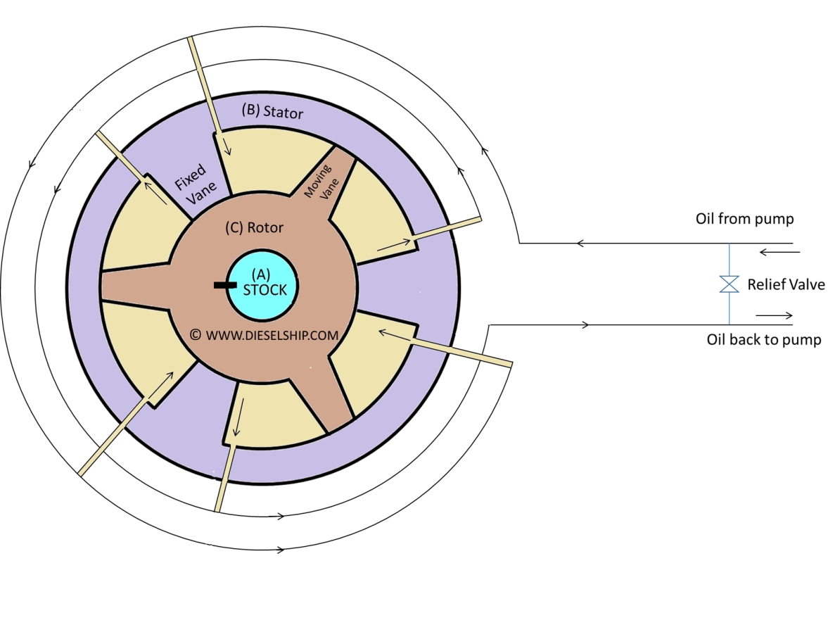
* The rotor C is fitted and keyed to a tapered rudder stock A, the stator B is secured to the ship’s structure. Fixed vanes, secured equidistantly in the stator bore and rotating vanes secured equidistantly in the rotor, form two sets of pressure chambers in the annular space between the rotor and stator.
* They are interconnected by a manifold. Fluid supplied at pressure to one set of these chambers will rotate C clockwise and the rudder will turn to port, or to starboard if the alternate set is put under pressure.
* The fixed and rotating vanes may be of spheroidal graphite cast iron. They are securely fixed to the cast steel rotor and stator by high tensile steel dowel pins and cap screws. Keys are also fitted along the length of the rotary vanes, for mechanical strength.
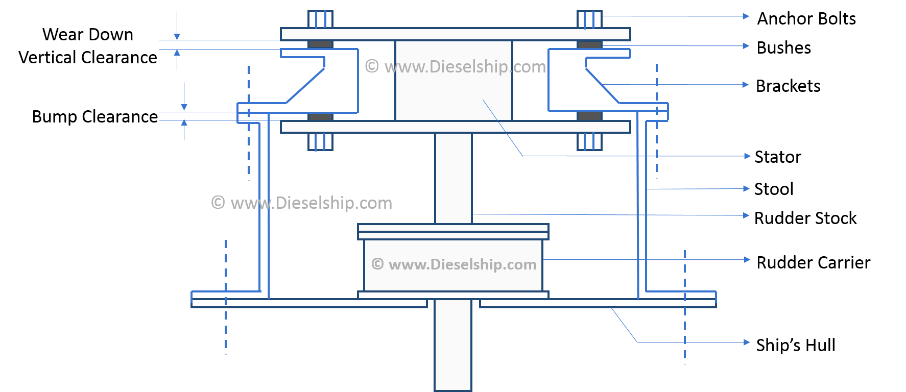
* Assembly of the gear would not be possible if the fixed vanes were keyed; they rely on the dowels to provide equivalent strength. The vanes fixing is considered to be of sufficient strength to make them suitable to act as rudder stops. Steel sealing strips, backed by synthetic rubber, are fitted in grooves along the working faces of the fixed and rotary vanes, thus ensuring a high volumetric efficiency, of 96—98% even at the relief valve pressure of 100 bar or over. Rotation of B is prevented by means of two anchor brackets, and two anchor pins. The anchor brackets are securely bolted to the ship.
* Vertical clearance is arranged between the inside of the stator flanges and the top and bottom of the anchor brackets to allow for vertical movement of the rudderstock. This clearance varies with each size of the rotary vane unit, but is approximately 38 mm in total and it is necessary that the rudder carrier should be capable of restricting the vertical movements of the rudderstock to less than this amount.
How the vanes are secured and the method of sealing the edges.
– All vanes are spheroidal graphite cast iron secured to the cast iron rotor and stator by high tensile steel dowel pins and cap screws.
– Keys are also fitted along the length of the rotary vanes, for mechanical strength. Assembly of the gear would not be possible if the fixed vanes were keyed; they rely on the dowels to provide equivalent strength. The vanes fixing is considered to be of sufficient strength to make them suitable to act as rudder stops.
– Steel sealing strips, backed by synthetic rubber, are fitted in grooves along the working faces of the fixed and rotary vanes, thus ensuring a high volumetric efficiency, of 96—98% even at the relief valve pressure of 100 bar or over.
Stator pressure chambers are usually duplicated.
The annular space between stator and rotor vanes are connected to two manifolds and form two sets of pressure chambers. Fluid supplied by the pump at a pressure to one set of these three chambers states the rudder in one direction and the fluid in the other set of three chambers squeezes out back to the pump.
State what considerations determine the number of vanes.
The rotary vane unit is normally fitted with three fixed and three moving vane, and permit a total rudder angle of 70° i.e. 35° in each direction. If larger rudder angle movement is required then only two fixed and two moving vanes will be used, which will permit an angular movement of the rudder of 130°. However the force on the vanes will have to be increased for the same torque as given by 3 vanes.
How the steering gear is locked for rudder maintenance.
Hydraulic Locking:
Isolating valves are provided at each cylinder or rotary vane chamber which when closed will hold the rudder by trapping the oil in the chambers. Isolating valves are also fitted to pumps so that a pump can be completely shut off from the circuit and removed for servicing while steering is continued with the other pump.
Mechanical Locking:
Usually the hexagon head of the steering gear is locked by placing a hexagon frame on it and locking it to the tiller. This method can be used as a secondary mean after locking it by hydraulic locking.
