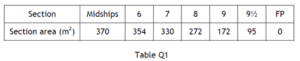
Q4. A ship of length 180 m, floats at its load draught with a displacement of 50000 tonne in sea water of density 1025 kg/m3. The longitudinal center of buoyancy (LCB) is 1.80 m aft of midships.
In this condition, the forward half of the ship displaces 23000 tonne and has a center of displaced volume (LCB) 33.0 m forward of midships. This part of the ship is to be replaced with a new forward half of similar length, but having new immersed cross section areas, to the same load draught, as given in Table Q1.
Calculate EACH of the following, for the new condition:
(a) The displacement of the ship;
(b) The longitudinal position of the ship’s center of buoyancy.
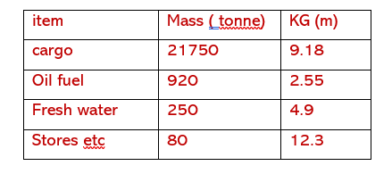
Q2. A ship has a lightship displacement of 9500 tonne and the height of the centre of gravity above the keel (KG) is 8.54 m. Loading now takes place as detailed in Table Q2.
Table Q2
In this loaded condition, the height of the transverse metacentre above the keel (KM) is 10.38m.
(a) Draw a curve of statical stability for the loaded vessel, using the cross curves of stability provided in Worksheet Q2. (12)
(b) Using the curve derived in Q 2 (a), determine the dynamical stability of the vessel up to an angle of 40o. (4)
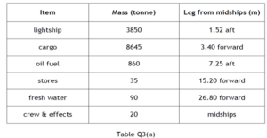
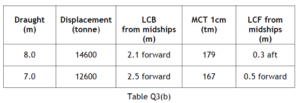
Q8. A ship of length 130 m is loaded as shown in Table Q3(a).
Table Q3(b) is an extract from the ship’s hydrostatic particulars and linear interpolation may be used to obtain data at intermediate draughts.
Determine the end draughts of the ship after loading has been completed.
Q2. A single screw ship with a service speed of 16 knots is fitted with a rectangular rudder, 6.5 m deep and 4 m wide, with its axis of rotation 0.4 m from the leading edge. At a rudder helm angle of 35 degrees, the center of effort is 32% of the rudder width from the leading edge. The force (F) on the rudder normal to the plane of the rudder is given by the expression:
F = 577 A v2 sin α (newtons)
Where:
A = area of the rudder (m²)
v = ship speed (m/s)
α = rudder angle (degrees)
The maximum stress on the rudder stock is to be limited to 70 MN/m2.
Calculate EACH of the following, for a rudder angle of 35 degrees:
(a) The minimum diameter of the rudder stock for ahead running;
(b) The speed of the ship, when running astern, at which the maximum stress Level would be reached.
Q4. A ship of length 145 m and breadth 23 m floats at a draught of 10 m in sea water of density 1025 kg/m³ with a block coefficient of 0.72.
A geometrically similar model 5 m in length, when tested at a speed of 1.48 m/s in fresh water of density 1000 kg/m³ gives a total resistance of 29.25 N.
Using the data given below, determine the service delivered power for the ship at the corresponding speed to that of the model.
Allowance for appendages = 5%
Allowance for weather = 16%
Quasi-propulsive coefficient (QPC) = 0.71
The frictional coefficient for the model in fresh water is 1.694
The frictional coefficient for the ship in sea water is 1.414
When speed is in m/s with index (n) = 1.825
Wetted surface area (m²) = 2.57 √(∆ × L)
Q8. A ship 156 m in length, 22 m breadth, displaces 19700 tonne when floating at a draught of 8 m in sea water of density 1025 kg/m3. The ship’s propeller has a diameter of 5.5 m, a pitch ratio of 0.9 and a blade area ratio of 0.45. With the propeller operating at 1.8 rev/s, the following results were recorded:
Apparent slip ratio = 0.05
Thrust power = 1250 kW
Propeller efficiency = 66 %
Calculate EACH of the following for the above condition:
(a) The ship’s speed; (3)
(b) The real slip ratio;(6)
(c) The thrust per unit area of blade surface; (4)
(d) The torque delivered to the propeller. (3)
Note: The Taylor wake function w, is given by w = 0.5 Cb – 0.05
Username or email address *Required
Password *Required
Note: Entering wrong username in the login form will ban your IP address immediately. Entering wrong password multiple times will also ban your IP address temporarily.
Log in
Lost your password? Remember me
No account yet?