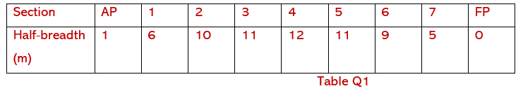
Q1. A ship 160 m in length has a load displacement of 20500 tonne and floats in water of density 1025 kg/m3. The load waterplane is defined by equally spaced half breadths as shown in Table Q1.
The following particulars are also available:
Centre of buoyancy above the keel (KB) = 4.264 m
Centre of gravity above the keel (KG) = 7.561 m
Centre of lateral resistance above the keel = 4.050 m
A rectangle tank, partially filled with oil of relative density 0.89 has overall dimensions of 10 m by 10 m, but is divided into two equal tanks by an oiltight longitudinal bulkhead.
Calculate EACH of the following:
(a) The effective metacentric height; (12)
(b) The angle to which the ship will heel when turning on a circular course of 400 m diameter at a speed of 16 knots. (4)
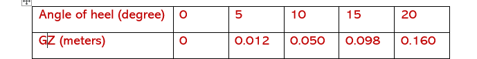
Q2. A ship of 25420 tonne displacement floating in sea water has 800 tonne of bunker fuel of density 895 kg / m3 in double bottom tanks which are pressed up full. In this condition the metacentric height is 0.25 m and the ordinates of the statical stability curve
Corresponding to this displacement are as shown in Table Q2.
Table Q2
The oil is transferred to a deep tank 4.85 m long by 18.2 m wide, situated on the ship's centreline. The centre of gravity of the fuel after transfer is 6.8 m above the original centre Determine EACH Of the following for the new condition:
(a) the final effective metacentric height; (3)
(b) the angle to which the ship lists; (7)
(c) the dynamical stability at 200 angle Of heel. (4)
Q3. A ship of length 110 m has draught marks 4.5 m aft of the forward perpendicular and 5.5 m forward of the after perpendicular. The draughts at the marks are 4.35 m aft and 3.85 m forward. For this condition, the following hydrostatic data are available:
LCF = 2.25 m aft of midships
Displacement= 6300 tonne
GML = 80 m
LCB = 0.6 m aft of midships
(a) The true mean draught; (4)
(b) The draught at the perpendiculars;(4)
(c) The draught at the perpendiculars;(4)
Q6. A single screw vessel with a service speed of 16 knots is fitted with an unbalanced rectangular rudder 6 m deep and 3.5 m wide with an axis of rotation 0.25 m forward of the leading edge. At the maximum designed rudder angle of 350 the centre of effort is 30% of the rudder width from the leading edge.
The force on the rudder normal to the plane of the rudder is given by the
expression:
Where:
20.2 A v2 a newtons
A rudder area (m2)
v ship speed (m/s)
- rudder helm angle (degrees)
The maximum stress on the rudder stock is to be Limited to 70 MN/m2.
(a) the minimum diameter of rudder stock required; (9)
(b) the percentage reduction in rudder stock diameter that would be achieved (7)
if the rudder was designed as a balanced rudder, with the axis of rotation 0.85 m from the leading edge.
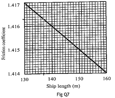
Q7. A ship 137 m long displaces 13716 tonne. The shaft power required to maintain a speed of 15 knots is 4847 kW, and the propulsive coefficient based upon shaft power is 0.67.
wetted surface area = 2.58
propulsive coefficient = ep/ sp
Values of the Froude friction coefficient for Froude’s Formula are given in Fig Q7, with speed in m/s and speed index (n) =1.825
Calculate the shaft power for a geometrically similar ship which has a displacement of 18288 tonne and which has the same propulsive coefficient as the smaller ship, and is run at the corresponding speed. (16)
Q8) The following data applies to a ship operating on a particular voyage with a propeller of 6 m diameter having a pitch ratio of 0.9.
Propeller speed = 1.85 revs/s Real slip = 33% Apparent slip = 6% Shaft power = 11000kW Specific fuel consumption = 0.205 kg/kWhr
(a) The ship speed in knots; (3)
(b) The taylor wake fraction; (3)
(c) The reduced speed at which the ship should travel in order to reduce the voyage consumption by 30%; (2)
(d) The voyage distance if the voyage takes 30 hours longer at the reduced speed; (4)
(e) The amount of fuel required for the voyage at the reduced speed. (4)
Q6) (a) With the aid of an outline sketch explain EACH of the following:
(i) Unbalanced rudder; (2)
(ii) Semi-balanced rudder; (2)
(iii) Balanced rudder. (2)
(b) State the principal advantage of fiiting a balanced rudder. (1)
(c) A ship travelling at full speed has its rudder put hard over to port, where it is held until the ship completes a full turning circle.
Describe, with the aid of a sketch, how the ship will heel from the upright condition during the manoeuvre. Illustrate the moments produced by the forces acting on the ship and the rudder. (9)
Username or email address *Required
Password *Required
Note: Entering wrong username in the login form will ban your IP address immediately. Entering wrong password multiple times will also ban your IP address temporarily.
Log in
Lost your password? Remember me
No account yet?