Q2. A ship of length 120m and breadth 16 m floats upright at a draught of 6.5 m in sea water of density 1025 kg/m3 and the height of the centre of gravity above the keel (KG) is 4.735 m.
Further hydrostatic data for this condition are as follows:
Centre of buoyancy above the keel (KB) = 3.2 m
Height of metacentre above the keel (KM) = 6.6 m
Waterplane area coefficient (CW) = 0.8
Block coefficient (Cb) = 0.7
In the above condition there is an empty rectangular wing tank 12 m long, 4 m wide and 6 m deep, adjacent to the hull and directly above a double bottom tank 1.2 m deep.
Calculate the angle to which the ship will heel when the tank is completely filled with fresh water of density 1000 kg /m3, assuming the ship to be wall sided over the change of draught. (16)
Q3. A ship of length 240 m has draught marks 6.0 m aft of the forward perpendicular and 10.0 m forward of the after perpendicular.
The draughts at the marks are 8.8 m aft and 7.6 m forward.
For this condition, the following hydrostatic data are available:
LCF = 2.4 m aft of midships
Displacement = 65000 tonne
GML =120 m
LCB = 1.4 m aft of midships
Calculate EACH Of the following:
(a) The true mean draught; (4)
(b) The draughts at the perpendiculars; (4)
(c) The longitudinal position of the centre of gravity. (8)
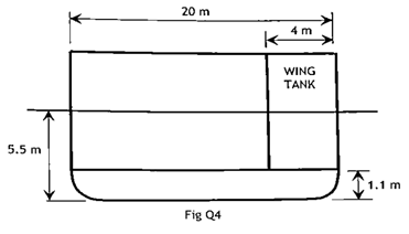
Q4. A ship of displacement 6000 tonne in Sea water of density Of 1025 kg/m3 has a breadth of 20 m and a draught of 5.5 m.
The area of waterplane is 1500 m2, KB is 3.2 m, KG is 4.8 m and the second moment of area of the waterplane about the centreline is 22000 m4.
A rectangular wing tank of length 10 m and breadth 4 m is situated above a double bottom of depth 1.1 m as shown in Fig Q4.
Calculate the angle of heel that would occur if the wing tank were bilged. (16)
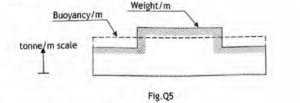
Q5. Fig.Q5 shows the distribution of weight per metre and buoyancy per metre for a freely floating vessel.
(a) Explain why the vessel must be:
(i) Of constant cross section.
(ii) On even keel.
(iii) Sagging.
(b) Sketch the expected shapes of EACH of the following diagrams explaining the reasons for the farm they take:
(i) Load diagram.
(ii) Shear force diagram.
(iii) Bending moment diagram.
Q6. A single screw ship with a service speed of 15 knots is fitted with a rectangular rudder, 5.5 m deep and 3.5 m wide with the axis of rotation 0.4 m aft of the leading edge. At a rudder angle of 35o, the centre of effort is 32 % of the rudder width from the leading edge. The force on the rudder normal to the plane of the rudder is given by the expression:
Fn=577 A v2 sin α newtons
Where;
A = Rudder area ( m2 )
v = Ship speed ( m⁄s)
α = Rudder angle ( degrees)
The maximum stress in the rudder stock is to be limited to 70 MN/m2.
Determine EACH of the following:
(a) The minimum diameter of the rudder stock required for ahead running; (9)
(b) The speed of the ship, when running astern, at which the maximum stress level would be reached.(7)
Q7. A ship 150 m tong has a load displacement of 27500 tonne in sea water of density 1025 kg/m3. To maintain a speed of 16 knots in the above condition of trials, a shaft power of 7860 kW is required.
SCF for trial condition = 1.08
SCF for service condition = 1.23
Quasi-propulsive coefficient (QPC) = 0.70
Transmission losses = 3%
Wetted surface area (m2) = 2.57 √∆L
Calculate the shaft power required in service for a geometrically similar ship of 22360 tonne load displacement operating at the corresponding speed. (16)
Note: The frictional coefficient for the 27500 tonne ship in sea water is 1.413
The frictional coefficient for the 22360 tonne ship in sea water is 1.415
The frictional coefficients are to be used with speed in m/s Speed index (n) is 1.825
Username or email address *Required
Password *Required
Note: Entering wrong username in the login form will ban your IP address immediately. Entering wrong password multiple times will also ban your IP address temporarily.
Log in
Lost your password? Remember me
No account yet?