Q1. At a draught of 1.0 m in sea water of density 1025 kg/m3 the displacement of a ship is 900 tonne and the height of the centre of buoyancy above the keel (KB) is 0.6 m.
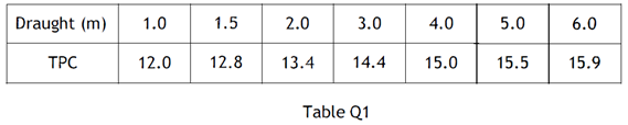
Values of tonne per centimetre immersion (TPC) in sea water for a range of draughts are given in Table Q1.
(a) Calculate EACH of the following for a draught of 6.0 m in sea water:
(i) The displacement; (4)
(ii) The height of the centre of buoyancy above the keel (KB). (6)
(b) At a draught of 6.0 m, the height of the longitudinal metacentre above the keel (KML) is 128 m and the second moment of area of the waterplane about a transverse axis through midships is 996728 m4.
The centre of flotation is aft of midships.
Calculate the distance of the centre of flotation (LCF) from midships. (6)
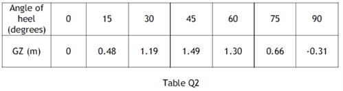
Q2. Table Q2 gives values of righting levers (GZ) relating to a ship of 12000 tonne displacement in a particular load condition:
In the above condition the ship has 320 tonne of fuel stored in a double bottom tank which has to be emptied for survey. This oil is transferred to a wing deep tank, through a transverse distance of 7.5 m and a vertical height of 5.25 m.
(a) Draw the amended curve of statical stability, neglecting the effects of free surface. (12)
(b) Determine EACH of the following, from the curve drawn in Q2(a):
(i) The angle to which the ship will list; (1)
(ii) The range of stability. (1)
(c) Determine the righting moment at an angle of 25o. (2)
Q3. A ship of 120 m in length has the following particulars when floating in sea water of density 1025 kg/m3.
Displacement = 10560 tonne
Draught aft = 6.93 m
Draught forward = 6.58 m
Longitudinal metacentric height (GML) = 125 m
Centre of flotation from midships (LCF) = 2.4 mf aft
Tonnes per centimetre immersion (TPC) = 19.9
Two tanks, each containing a substantial quantity of water ballast, are situated with their centres of gravity 30 m aft of midships and 55 m forward of midships. The vessel is required to enter dock with draught aft 6.60 m and a trim of 0.50 m by the stern.
Calculate the amount of ballast to be discharged from EACH tank. (16)
Q4) With reference to the inclining experiment:
(a) State the purpose of the experiment and when the experiment should be performed during the life of a ship; (2)
(b) Explain the procedure immediately prior to the experiment; (4)
(c) Describe the procedure for the experiment; (4)
(d) List SIX precautions to ensure acceptable accuracy of results. (6)
Q5. A box barge Of 70 m length has a hull mass of 560 tonne evenly distributed over its length.
Bulkheads located 5 m from the barge ends form peak tanks that remain empty.
The remainder of the barge length is divided by two transverse bulkheads into three holds of equal length.
A total of 1680 tonne is loaded, one quarter of which is placed in the middle hold, the remainder being equally distributed over the two outer holds.
using Worksheet Q5, draw EACH of the following on a base of barge length:
(a) Curves of weight and buoyancy per metre; (4)
(b) Curve of toads; (3)
(c) Curve of shearing forces; (4)
(d) Curve Of bending moments. (5)
Q6. A single screw vessel with a service speed of 15 knots is fitted with an unbalanced rectangular rudder 6 m deep and 4 m wide with an axis of rotation 0.2 m forward of the leading edge. At the maximum designed rudder angle of 35o the centre of effort is 30% of the rudder width from the leading edge.
The force on the rudder normal to the plane of the rudder is given by the expression:
Fn= 20.2 A v2 α newtons
Where: A = Rudder area (m2)
v = Ship speed (m⁄s)
α = Rudder helm angle (degrees)
The maximum stress on the rudder stock is to be limited to 70 MN/m2
Calculate EACH of the following:
(a) The minimum diameter of rudder stock required;(9)
(b) The percentage reduction in rudder stock diameter that would be achieved if the rudder was designed as a balanced rudder, with the axis of rotation 1.0 m aft of the leading edge. (7)
Q5. A ship model of length 6 m has a wetted surface area of 6.62 m2. When tested in fresh water of density 1000 kg/m3, at a speed of 1.8 m/s, the total resistance was measured at 48 N. This tank speed corresponds with a trial ship speed of 17.5 knots in sea water of density 1025 kg/m3, which is achieved when the shaft power is 8720 kW, when the propulsive coefficient is O. 67. Calculate the Ship Correlation Factor (SCF) for the ship in this trial condition. (16) Note: The frictional coefficient for the model in fresh water is 1.655 The frictional coefficient for the ship in sea water is 1.413 Speed in m/s with the speed index (n) for ship and model 1.825.
Q8. A ship of 30800 tonne displacement has a length of 150 m, breadth of 26.5 m and floats at a draught of 10.5 m when in sea water of density 1025 kg/m3.
The ship’s propeller has a diameter of 6.5 m with a pitch ratio of 0.8.
When the propeller is operating at 1.75 revs/sec, the real slip is 32% and the thrust power is 6800 kW.
The thrust power is reduced to 5500 kW and the real slip increases to 35%. It can be assumed that the thrust power is proportional to (speed of advance)3.
Calculate EACH of the following for the reduced power:
(a) Ship speed; (11)
(b) The propeller speed of rotation; (3)
(c) The apparent slip. (2)
Note: Wake fraction = 0.5 Cb – 0.05
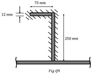
Q9. A ballast tank watertight bulkhead 5.0 m deep is stiffened by vertical angle bar Stiffeners 250 mm x 75 mm x 12 mm thick, spaced 610 mm apart. The ends of the stiffeners in contact with the tank top are welded all around as shown in Fig Q9 and the thickness Of the weld is 6 mm.
The bulkhead has sea water of density 1025 kg/m3 one side to a depth of 4.5 m.
Calculate the shear stress in the weld metal. (16)
The bulkhead has sea water of density 1025 kg/m3 on one side to a depth of 4.5 m.
Calculate the shear stress in the weld. (16)
Username or email address *Required
Password *Required
Note: Entering wrong username in the login form will ban your IP address immediately. Entering wrong password multiple times will also ban your IP address temporarily.
Log in
Lost your password? Remember me
No account yet?