Academics – Electro-Technology : 2025/MAR/04
Question
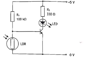
Q20. Fig shows a flame failure detector circuit which uses a light dependent resistor LDR, a light emitting diode LED, and a transistor switch. When the transistor is FULLY ON the collector current is 10 mA. The base current is negligible and the collector emitter voltage VCEMIT is 0.15 V.
a) Explain the operation of the circuit.
b) Calculate the minimum LDR resistance at which the transistor turns on.
c) Calculate EACH of the following when the transistor is FULLY ON:
(i) the voltage across the LED.
(ii) the power supplied to the circuit.
d) Describe the change in circuit operation if the positions of LDR and R1 are swapped.
Asked in Year/Month/Ques No.
Hello Guest User,
Answers are available via our app only.
Please buy a membership plan and login via our app to view answers.
Please buy a membership plan and login via our app to view answers.
Download our App