Impressed current cathodic protection (ICCP) on ships

Impressed current cathodic protection on ships
Galvanic corrosion
- When 2 dissimilar metals are in contact with each other in the presence of a corrosive medium (electrolyte), the more active metal in the galvanic series acts as an anode and undergoes corrosion.
- This means, in a galvanic series of metals, the more active metal acts as anode and undergoes corrosion and the less active metal acts as a cathode and stays protected.
- Impressed current cathodic protection (ICCP) on ships system make the hull to remain always cathode by keeping the Potential difference to a minimum and introducing a current opposite to the natural corrosion current, thereby protecting the anode and avoiding corrosion.
Electro-Chemical Attack
- The outer surface of a ship’s hull is subjected to electro-chemical attack by corrosive currents that flow between areas of the hull which are at slightly different electric potentials.
- Dissimilar metals, variations in structural and chemical uniformity in hull plates and welding, differences in paint thickness and quality, water temperature, salinity and aeration all combine to cause areas of the hull to become either anodic (positive) or cathodic (negative).
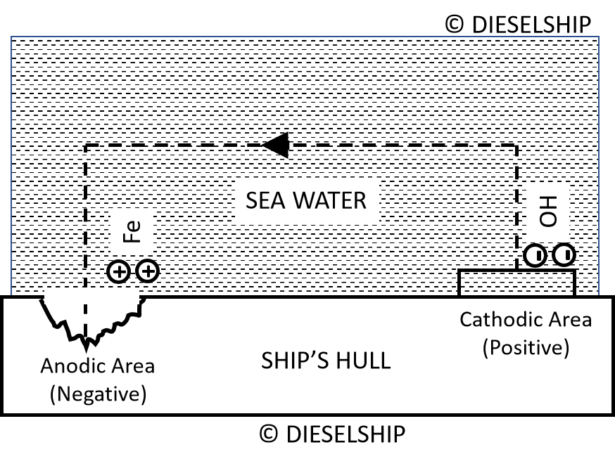
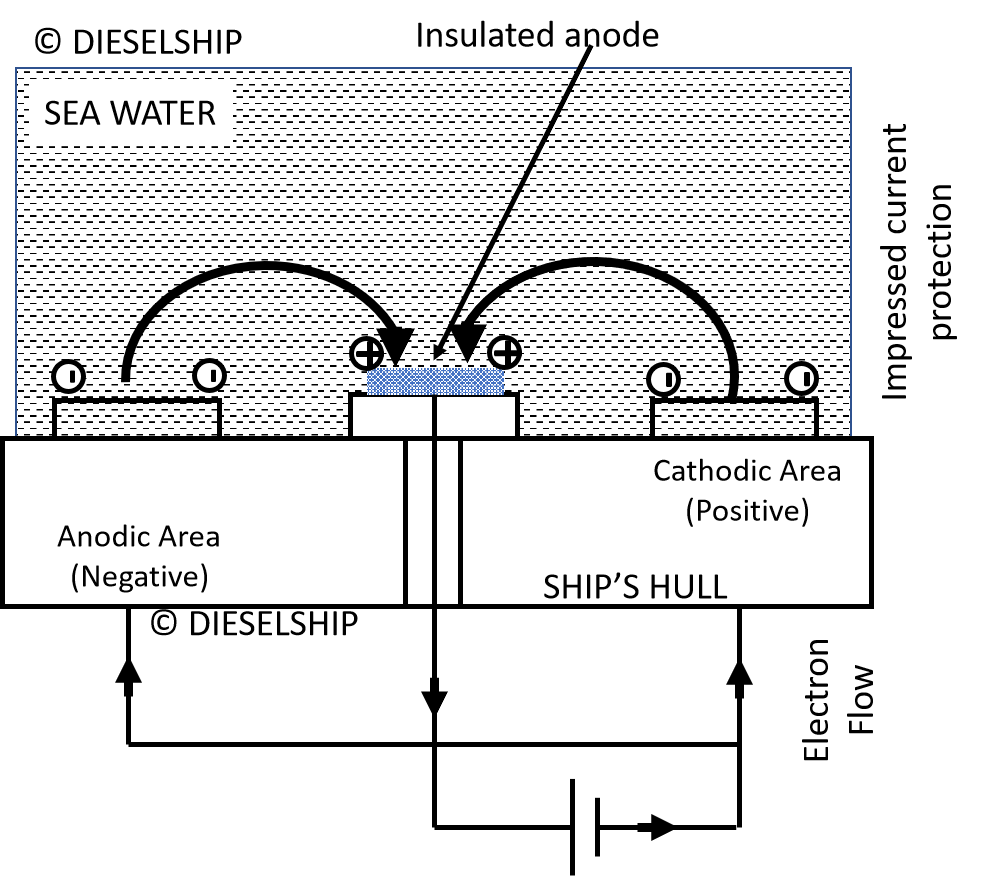 Fig above shows that in the hull, electrons flow from anode to cathode leaving positively charged iron ions at the anodic area. At the cathode the effect of the arrival of electrons is to produce negatively charged hydroxyl ions (OH) by electrolysis of the sea water.
- These negative ions flow through the sea to the anodic area where they combine with the positive iron ions to form ferrous hydroxide Fe(OH)2.
- This ferrous hydroxide is further oxidised by dissolved oxygen to form ferric hydroxide Fe(OH)3 which is rust. Thus the anodic area is gradually corroded away whilst no corrosion takes place at the cathodic area.
How to prvent this corrosion?
- This naturally corrosive action can be overcome if the complete hull is made cathodic, i.e. electrons are allowed to arrive at the hull surface and produce ,negative hydroxyl ions but no electrons leave the hull to produce positive iron ions.
- This is achieved by fitting insulated lead or platinised titanium anodes to the hull and applying a positive d.c. potential to them with respect to the hull.
- The negatively charged hydroxyl ions (OH) now pass to the insulated lead anodes causing the lead surface to change to lead peroxide pbo2.
How much of current to be injected? is there a limit??
- The current injected is of such a value that it just overcomes the original corrosion current and gives rise to an impressed protection current which flows-in the complete circuit.
- The value of protection current must be critically controlled to just prevent corrosion, is beyond this value.
If the current injection is too much, then the rate of release of hydroxyl ions will cause sponginess and flaking of the anti-fouling paint.
- The correct value of protection current can be determined by reference electrodes. These are either of zinc or silver attached to the hull, but insulated from it, below the waterline.
- The reference electrode voltage may, therefore, be used to monitor the protection, but
more important, is used as the signal source to automatically regulate the value of protection current.
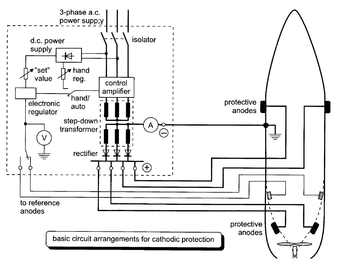
Typical Impressed current cathodic protection (ICCP) on ships
Picture source : DT Hall book
- Impressed current cathodic protection (ICCP) on ships consists of a number of anodes (lead or platinised titanium) fitted to the hull at selected places below the waterline, and control equipment which automatically regulates the anode current to the required value.
- Direct current is supplied to the anodes, after transformation and rectification, from the ship’s 440 V 60 Hz, 3-phase a.c. distribution system. The control equipment comprises reference electrodes, an amplifier assembly and one or more transformer rectifier units.
- The anode current control is usually regulated by electronic thyristor controllers and the diagram outlines a typical scheme.
- The control equipment automatically monitors the size of anode current required which will vary with the ship’s speed, water temperature and salinity, condition of paint work etc.
- Typical anode current densities range from 10 mA/m2 to 40 mA/m2 for the protection of painted surfaces and 100 to 150 mA/m2 fbr bare steel surfaces.
- The total impressed current for a hull in good condition may be as low as 20 A. Maximum controller outputs may be up to about 600 A at 8 V. Cathodic protection does not appear to deter molluscular growth on the ships hull, so a top coat of anti-foul (poisonous) paint is still necessary.
Picture source : DT Hall book
- Typical reference and main anode outlines are shown in Figure above. Monitoring facilities in the cathodic protection control cabinet may provide measurements of:
- Reference electrode voltage (hull potential)
- Amplifier output voltage
- Total anode current
- Individual anode current
- Measurements should be regularly logged together with the ship operating conditions,
e.g. location, draught, water temperature, etc. - Changes in underwater hull area, speed, water temperature/salinity and paint condition will all cause the anode currents to vary. The hull potential should, however, remain constani in a properly regulated system..
- Although the reference electrodes and the monitoring facilities give a reasonable day to day check they are 0nly measuring in the vicinity of the fitted electrodes.
- When the ship is moored singly or stopped at sea, voltage readings can be taken between a portable silver or zinc test electrode and the ship’s hull. This portable electrode is lowered 2-3 metres below the water surface and as close as possible to the hull at specified positions around the ship.



Text well presented
If cell 1 and cell 2 value is going to ninus 20 to 40 then wahts the couse ? Is it healthy?
After 2 month of drydock