Withdrawal of Propeller shaft, survey and assembly
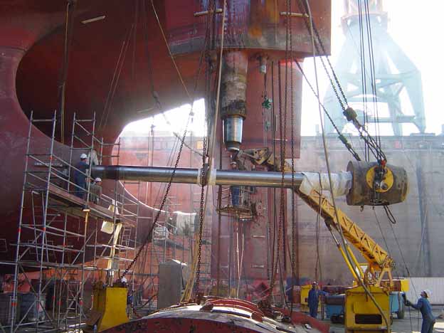
Withdrawal of Propeller shaft, survey and assembly
propeller shaft Withdrawal,survey assembly
propeller shaft Withdrawal,survey assembly .All large single screw ocean going ships have solid flanged propeller shafts, which necessitates the withdrawal of the shaft within the machinery The Rudder is ;positioned just behind the propeller and hence prevents the outward withdrawal of the shaft . This is another reason to be considered even if the flange coupling is a muff type coupling.
The general scheme of withdrawal is therefore as follows:
- The intermediate shaft is disconnected at both ends by dismantling all the coupling
- Dismantling all the holding – down bolts of the plummer/pedestal
- lifting up and holding the intermediate shaft in the lifted
- Jacking off the propeller after the shaft nut is dismantled and withdrawing the shaft inwards and finally resting it in the space created by the intermediate.
Detailed procedure of dismantling
(1) Intermediate shaft coupling bolts forward and aft slackened ,eased and ready for removal with couple of bolts at both ends in place to prevent turning of the propeller shaft when dismantling the propeller nut.
In shipyard practice the ship is moved by tugs from repair berth to the dry dock and engine is not used. Hence this job can be commenced and completed before ship enters the dry dock.
(2) Plummer block holding-down bolts dismantled and intermediate shaft kept ready for lifting.
(3) Propeller cone dismantled , propeller nut key dismantled and propeller nut taken out (Fig: Propeller nut locking device)
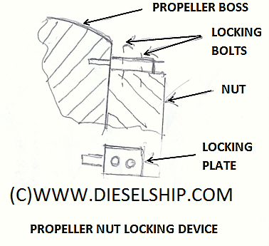
Propeller nut locking device
(4) Propeller blades position adjusted and weight of propeller supported by slings and chain blocks which are suspended from bridles(harness) properly rigged from poop bollards. (Fig: Propeller slung on chain blocks)
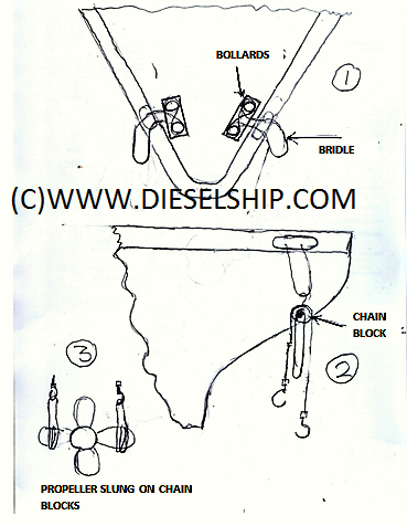
Propeller slung on chain blocks
(5) Intermediate shaft along with plummer block lifted up and held in place by attached chain blocks.
(6) Chrome liners forward and aft flange connections uncoupled and chrome liners pushed in
(7) A light mark(line) made on taper of shaft in line with forward edge of the boss made. Reference for limit of push up during assembly.
(8) Strong back of propeller withdrawal tool attached with propeller nut removed and refitted in after turning it to enable the inbuilt jack to force on the strong-back. (see sketch given under Fig:Dismantling arrangement with pilgrim nut)
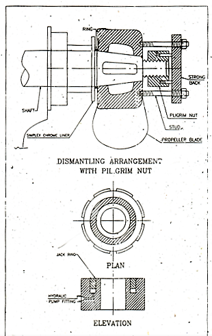
Dismantling arrangement with pilgrim nut
(9) If Pilgrim nut use pilgrim nut in dismantling mode. If no Pilgrim nut provided use shaft end to support jack supplied by yard for forcing out the propeller.
The pressure to be applied on the pilgrim nut or jack should be at least 50% greater than the final tightening pressure used during the last shaft survey which can be verified from last shaft survey records given by the shipyard where the survey was carried out, or from shipyard records where ship was built if this is the first special survey.
(10) When propeller jumps off taper withdraw propeller shaft completely whilst the weight of the propeller is held on the chain blocks.
(11) Lower propeller down to rest and keep it properly supported.
(12) Both seal boxes removed from location and sent to shops for dismantling , cleaning and renewal of seals and chrome liner.
Scope of survey
The following activities constitute the scope of survey:-
(1) General i inspection of shaft. The shaft after withdrawn inwards is cleaned thoroughly after it is properly supported on wooden blocks placed on the plummer block stool. A general inspection is carried out.
(2) General inspection of stern tube internal ;- The stern tube internally is cleaned thoroughly after draining all the oil. The white metal bushes forward and aft are checked for cracks, pitting and looseness of metal.
(3) Calibration of bushes using inside micrometer. Readings taken at at least at six locations , readings taken in directions P-S and T-B. Readings are recorded as calibration inspection records issued by shipyard.
If the calibration shows excessive wear the bushes have to be remetalled and suitably machined.
(4)Magna flux checking for cracks on shaft taper and keyways. This is a statutory requirement as per classification rules and is carried out by a powerful horse shoe electro magnet fed by a 12 volt portable battery. When a light oil sprayed on the surface and iron filings spread on the oil, causes the iron filings to move and collect along the surface cracks, when the surface is magnetized by the electromagnet (Fig : Crack testing of propeller)
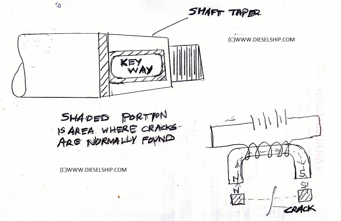
Crack Testing on propeller shaft
If cracks are found they are marked and removed by grooving through. Using a disc grinder, till the crack is completely removed lengthwise and depth wise. The groove edges are then rounded off to prevent stress concentration at these locations. The grooves are left without any build up or filling . This is a requirement on shafting systems to prevent fatigue conditions in the shafting system.
The crack locations and their grooves are mapped and recorded in the survey report for future reference. The presence of these grooves do not affect the strength of the shaft as far as the depth of the grooves are within the design diameter of the shaft. Normally the propeller shaft has a larger diameter than the intermediate shaft since the stresses on propeller shaft are higher than the stresses on the intermediate shaft. The propeller shaft is subjected to the full power torque as well as the bending moment caused by the overhang of the propelled at the shaft end, whereas the inter mediate shaft is subjected to only the full power torque.
Generally the appearance of surface cracks caused by fatigue is rare and most of the ships pass this test without any cracks found, but for reliability reasons the classification societies have made this test mandatory.
Verification of tightness of nut on shaft
The nut is mounted on the shaft threads screwed in and the radial play as well as the axial play are noted.
Internal inspection of propeller boss and inspection of blades for noting cavitation pitting as well as cracks at blade tips . Recommendations will be given for suitable repairs.
Assembly of propeller shaft and propeller
The forward and aft seal boxes are dismantled in the workshop. The box is made in two halves for enabling dismantling and renewing seals in afloat or dry dock situation without dismantling the shaft. The seals and chrome liner are renewed . Some superintendents economize by retaining the chrome liner and by machining the liner surface up to i mm so that the grooves caused by the seal disappear and give a smooth surface throughout. But this is not a good practice since with reduced diameter of the chrome liner the garter spring pressure on the surface is reduced and the seals are likely to leak . The sketch given below shows the aft seal box with all its components exposed. (Fig :Simplex stern tube seal)
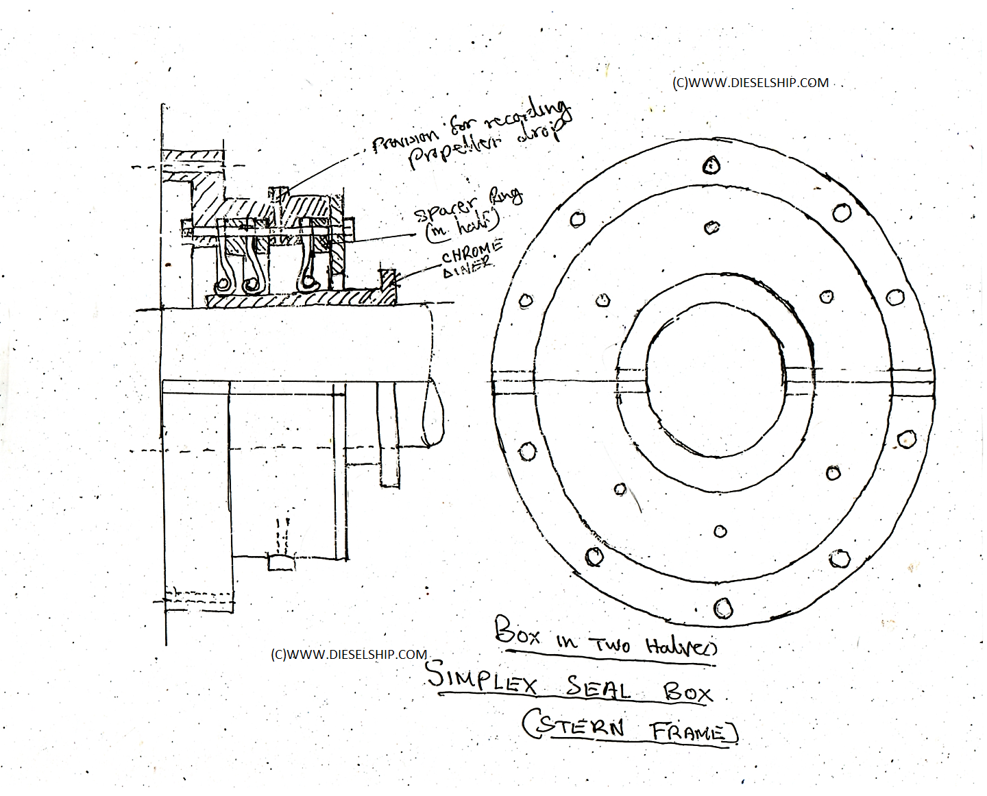
Simplex stern tube seal
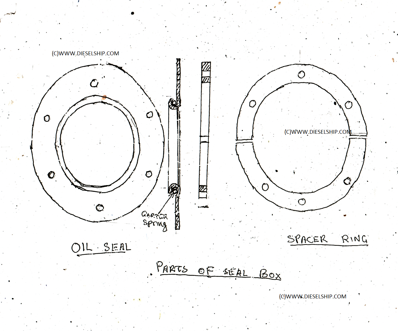
Oil seal and spacer ring
(1) The Assembly of seal gland boxes with new chrome liners forward and aft are fitted in their respective positions with a cellophane cover to prevent dust entering the seal box.
(2) The propeller is lifted , positioned and supported to receive the propeller shaft.
(3) The propeller shaft is inserted till it enters and sits on the propeller taper. The shaft is pushed in carefully to prevent the edges of the taper surface from damaging the white metal surface. Plenty of oil is smeared on the surface of the shaft to reduce friction whilst being pushed
in.
(4)The propeller nut is tightened sufficiently with spanner till it cannot move any further.
(5)If nut is pilgrim type hydraulic forcing can be done using a dial gauge to register amount of movement of propeller on taper. Simultaneously the forcing load on the pilgrim nut is also registered. (Fig :Fitting and tighteneing arrangement with pilgrim nut)
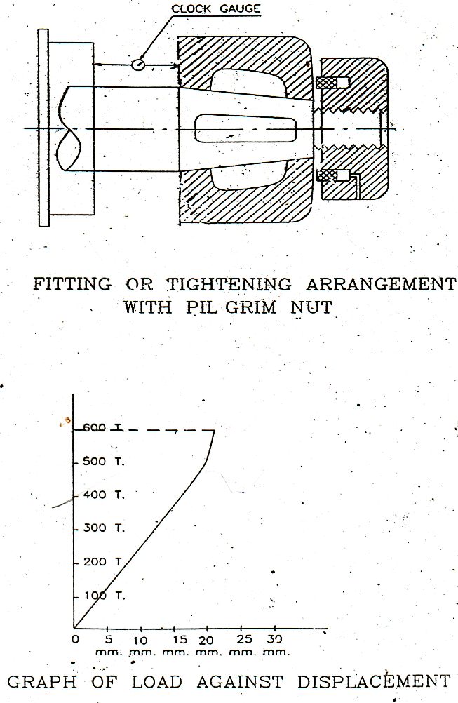
Fitting and tighteneing arrangement with pilgrim nut
(6)The propeller should be forced only till its forward edge reaches the reference mark made before dismantling
(7) The intermediate shaft inserted in place and connection of coupling bolts and plummer block attachment continues till completion.
(8) On propeller end propeller nut tightened to its mark or locking position and locking plate fitted.
(9) Chrome liner flange aft attached to propeller with new joint between chrome liner flange and propeller.
(10) Forward seal chrome liner is similarly attached to shaft half collars fitted in position.
(11) Propeller cone filled with new tallow and fitted in place.
(12) Propeller stern tube oil tank filled with new oil, air purged and shaft given two turns using turning gear to ensure aft seals are tight. This the leak test to be carried out to ensure the seals are tight and is also simultaneously checked for forward seal.
(13) Cone bolts cemented. Propeller drop taken and recorded and rope guard welded in place
The sketch of the assembled shaft and propeller is shown as under.(Fig: Sterntube shaft and oil seal) There is no need for an alignment check , since the coupling bolts go at the same locations (the bolts are correspondingly numbered and marked on holes as well as bolts.) The shims under the plummer block are similarly marked and go to their same locations as marked.
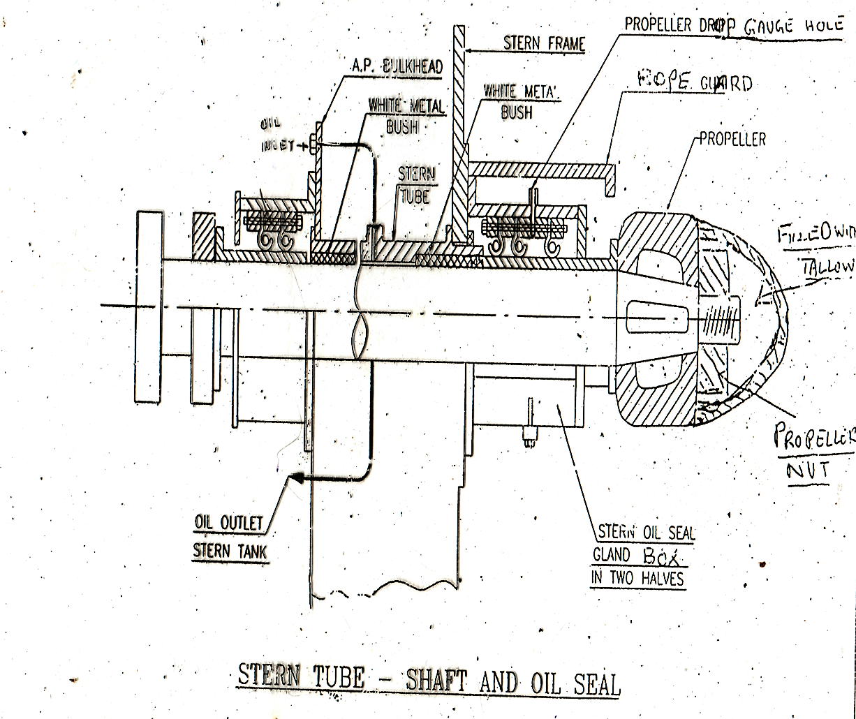
Sterntube shaft and oil seal
Sea water cooled/lubricated stern tube and shaft:-
This is the oldest existing system and is now being used in small sea going ships and in – land sea vessels. The average diameter size is restricted to not more than 250 mm.
The main disadvantage of this system is that the seawater being corrossive can corrode the portion of shaft exposed to the sea water. For this reason the portion of shaft exposed to the sea water is sheathed by a bronze liner shrunk fit on the shaft. But even with this precaution sand along with sea water has a free entry into the shaft. Sand being a hard material erodes the bush material which is Lignum vitae a natural hard wood heavier than water, and is in short supply these days. The bushing is now substituted by a patent hard rubber called Cutlass rubber or Railko a synthetic fibre material. All these materials also get eroded by the sand entering with the sea water. The leakage of sea water into the machinery space is prevented by a conventional gland and stuffing box packed with hemp packing rings.
With the progressive wear of the bushing the shaft tends to whirl thereby causing excessive strain on the stuffing box and leakage of sea water into the machinery space is increased in a short duration after dry docking. At times the leak is too much and nearly uncontrollable, even after fully tightening the gland, that a diver has to be employed in port to temporarily stop entry of sea water, whilst the packings are being renewed. This is a common feature of this arrangement.
At every shaft survey the bush strips or the cutlass bush has to be renewed since the wear is high. In oil lubricated stern tubes the wear is minimal and re -metalling of bush. It happens after about twenty years in service. This is an approximate and average estimate. The average working clearance is about 4mm at renewal time and reaches 10 mm at renewal time.
The method of withdrawal for survey and refitting are sam,e as in the case of oil lubricated shaft systems .
Development of the Keyless propeller shaft
To appreciate the need for key less shafts an historical review of the development of the shaft system study is necessary.
During the fifties of the last century the average size of ships were in the region of 6000 to 7000 tons displacement and there were a few ships over 10000 tons displacement. Most of these ships had conventional shafting systems , sea water lubricated. In this era the mode of tightening large bolts was by brute force using heavy sledge hammers. The limitation of tightening was observed by a rule that before opening a nut a suitable mark is made on the nut flat side and a corresponding mark made on the part, and when tightening if both marks coincide at the maximum tightening effort, it is considered fully tight. This used to be the procedure for tightening cylinder head covers and all running gear bearing bolts of the main engine. The process of tightening was by slogging on a short ring spanner by a heavy sledge hammer.
In the case of the propeller shaft ,for withdrawal purpose in dry dock the same procedure was used. In this case the hammer was heavier weighing about 200 kgs slung from a support at the stern frame by a rope and made to swing from a higher position so that it struck on the spanner head with a strong impact causing the nut to ease off.
When assembling the same method was used to push up the boss on the taper till it reaches the mark by slogging on the spanner to start and move the nut.
To free the boss from the shaft taper , steel wedges were inserted between the stern frame post and the propeller boss and the wedges were slogged in the same manner till the propeller jumped off the taper. In some adamant and difficult situations application of heat by large gas torches was resorted to and had to be done very carefully to prevent cracking of the propeller boss.
As ship sizes started increasing the shaft diameters and propeller sizes also increased accordingly and the primitive method of tightening or slackening had to give way to the use of hydraulic force which was controlled ,shock free and hence safe as well as easy to use. Special hydraulic jacks were developed to cater to these needs .
About the same time the formation of surface cracks on shaft tapers was observed in many ships of higher tonnage. This made the classification societies to contemplate on why these cracks were occurring and all leading classification societies broke their heads on finding the cause of this phenomenon . In this matter LLOYDS REGISTER has done considerable work by publishing and reading technical papers at various conferences and marine seminars. The invention of the Pilgrim nut is credited to the principal surveyor of Lloyds register about that time and the name he gave to this nut is pilgrim named after a religious preacher named Bunyon who happened to be his ancestor. This man wrote a book called pilgrim’s progress, a non detailed text book used in many convent schools to teach moral science. Hence the name pilgrim nut.
As an example, during the course of their research they observed that the push up load on the propeller during assembly is about 700 to 800 tons . this is easily found out in a jacking device which gives the push up load as P* The jack constant , where P is the oil pressure at the final step given in KN per mm2 and the jack constant is given as the cross section area of the jack in mm2 .
All keyed shafts have a taper of 1:14 as per class rules. The taper ratio defines the taper angle and is the Tan of the taper angle. For a push up load of 700 tons the normal reaction on the taper face is 700*14* 9.81=96138 KN. The more accurate reaction is 96380KN. Assuming the coefficient of friction to be 0.3 and assuming a mean radius of 160 mm the frictional torque preventing slippage between propeller and shaft is given as 96380*0.3*0.16 = 4626 KNM. Assuming the shaft power at service speed is 3500 KW at 115 RPM the shaft torque is given by 290.6 KNM. This calculation proves that the slipping torque is at least 14 to 15 times greater than the service and even the maximum power the engine can continuously develop. This calculation led to the thought that the key is redundant and can be done away with.
The keyway on the shaft taper is a source of defects leading to fatigue cracks developing because of the sudden change on the surface shape leading to stress concentrations around the keyway because of its sharp corners. If the key and keyway are eliminated about 75% of this problem is solved. Hence the need for keyless propeller shafts.
This problem came to light only when powers started increasing. Larger powers require larger diameter propellers for operating at same shaft speed. Proportionately the mass also increases considerably. A bulkcarrier or tanker of 80000 DWT will have a propeller weighing 35 Tons. Such a large mass contributes a sizeable bending moment at the commencement of the taper on the shaft because of the overhang of the propeller from the stern boss on the stern frame. This bending moment contributes to the torque causing an increase in the stress level at the surface of the taper. It is understood as follows.
The shaft torque formula is given by
T/J =ft /R , Where
T is the torque transmitted and resisted
J is the polar second moment of area of cross section of shaft.
Ft is the maximum stress (torsional) at the shaft surface.
R is the radius of the shaft(half dia).
This formula is true for only a torque to be transmitted, however when it is coupled with a sizeable bending moment the formula gets modified to:
? (T2+ BM2 ) /J = ft / R
It will be observed that this ft is larger than the previous ft proportionately and is called the principal stress which is proportional to ? (T2+ BM2 ) and is represented by the vector diagram as shown under, where FT is the principal stress (Fig: Vector Diagram)

Vector Diagram
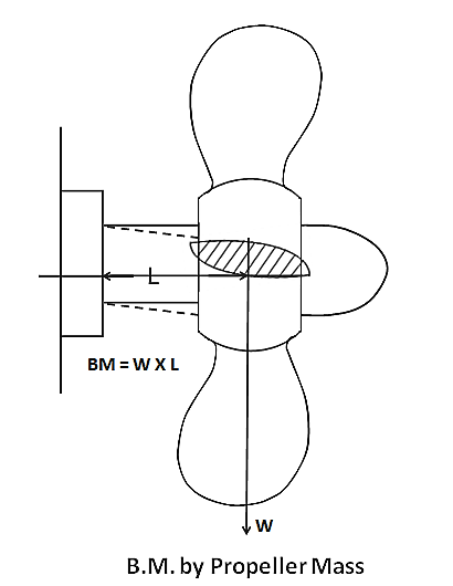
The bending moment causes the upper surface to strain in the tensile mode and the same surface when it comes down after half a revolution strains in the compressive mode. The Principal stress changes direction every half revolution or the alternating frequency is twice the RPM. leading to fatigue condition at the area around the bigger end of the taper. This is true for large ships having heavy propellers It may be concluded as follows:
Fatigue effects are predominant around the keyway because of sudden change of shape or surface, and around or throughout the circumference around the larger end of the taper because of change in direction of the principal stress occurring at a high frequency.
The classification societies recommended the elimination of the key and keyway, but at the same time they wanted to play safe and so they recommended two changes initially :
(1) The taper ratio to be increased from 1:14 to 1;18 or 1;20 .
(2) A cast iron sleeve to be placed between shaft taper and propeller boss to increase the coefficient of friction. The slipping torque is considerably increased by reducing the taper angle and increasing the coefficient of friction.
Initially some ships were fitted with keyless shafts and cast iron sleeve fixed firmly on the shaft using Araldite impregnated at a high pressure at the joint, but this system proved a failure as slippage of the joint occurred in some ships. A sketch showing this arrangement is shown under.
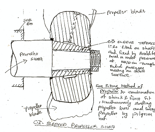
Sleeved propeller shaft
It was then considered to shrink fit the cast iron sleeve on the shaft taper . This method of fixture also failed because the locked in shrinking stress is not uniform since the grain size of cast iron matrix is not uniform and free graphite is found in the matrix which causes non uniform stress in the shrink leading to breakage/ cracking of the sleeve .
The present confirmed method is to force fit the propeller directly on the shaft taper.
(H) Method of fitting keyless propellers:-
The present method of fitting the propeller is called ‘ Wet fit method”. In this method the shaft taper is either 1;18 or 1;20 as per the individual classification rules. The propeller boss has a hole connecting the boss surface to the hollow core and the boss is pressurised by high pressure hydraulic fluid injected into the boss by a high pressure pump and at the same time pressurising the pilgrim nut for fitting and withdrawal. In all other respects the method is similar to the keyed propeller shaft fitting and withdrawal. This method uses force fit coupled with shrinkage to give a much higher grip than keyed propellers. The method of fitting is shown in sketch given as under.
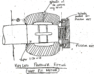
Keyless propeller fitting (Wet Method)
The classification societies recommend fitting keyless propellers for large ships to avoid fatigue cracking to occur on the taper fitting surface with the following conditions:
(1) the survey interval is enhanced to ten years , provided that at every dry docking the seals are subjected to a leak test similar to the keyed shaft assembly procedure.
(2) The condition of the lub oil is tested every six months at a laboratory approved by the classification society.
(I) Renewal of seals in afloat condition or in dry dock without withdrawal of shaft as well as chrome liner :-
At times occasionally the aft seal starts to leak and develop into a big leak within a few days making it necessary to either dry dock the ship or renew the seals in afloat condition. The reasons for the seals to leak are as follows:
(1) Some gritty matter like sand can get between the seals and the chrome liner and erode the seals and cause grooving of the liner surface leading to leakage.
(2) If the liner has been machined by 1mm during last dry dock, the spring pressure is reduced and can contribute to the leakage.
(3) The viscosity of the oil has reduced caused by using oil of lower viscosity as recommended by the shore office or the oil company.
The procedure adopted in carrying out this repair in dry dock is as follows:
(1) The seal box (aft) is made in two halves to facilitate this repair , and this is dismantled along with the spacing bolts of the seals. The box along with spacer rings are dismantled completely , leaving the seals on the chrome liner.
(2) The old damaged seals can be cut and removed .
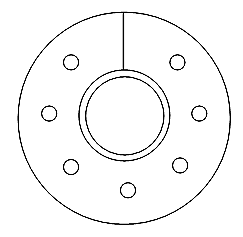
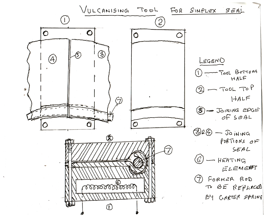
(3) The new seals one by one are slit , opened and mounted on the shaft forward of the chrome liner , the slits are vulcanised by a portable vulcanizing tool and then placed on the chrome liner. The process of slitting and vulcanizing is shown in the sketches given bellow. vulcanizing is rubber welding and is commonly used in tyre tube punctures.
(4) The three vulcanized seals are mounted on the chrome liner. The chrome liner is shifted forward after disconnecting it from the propeller . A split liner about 6mm thick is introduced between the propeller boss and the chrome liner so that the locations of the seals on the chrome liner are changed and fit on an unworn surface , avoiding the grooves formed. The split liner is made of bronze to avoid corrosion.(Fig 14) The arrangement is shown in sketch given below. After assembly of the seal box an oil leak test carried out and rope guard fitted back.
(Fig 14)
(5) This same repair can be done in afloat condition, provided the ship is in ballast condition. The ballast can be so arranged to have the aft peak tank empty and forepeak filled up along with the forward D.B. tanks pressed up so that the ship trims by head and brings the stern tube opening out of the water by at least over 15 cms.
A secure stage is built around the stern frame so that workmen can safely stand in the staging work safely. This job has to be done at a repair yard on the repair berth or at any port or repair berth.
Renewal of propeller shaft using Spare propeller shaft
During the process of shaft survey, if the depth of the cracks after grinding it off shows a measured depth greater than the rule permits, the classification society will recommend renewal of the shaft. All ships having keyed propeller shafts carry a spare propeller as a rule requirement . The provision of a spare shaft on board eliminates long periods of idle layup and unemployment since the propeller shaft is a ship specific item and to order a shaft will take minimum six months for delivery including shipping time.
I was witness to renewal of the shaft during dry dock when surface cracks appeared on two occasions of shaft survey within a span of 5 years and the classification society recommended renewal of the shaft.
The procedure is as follows.:
(1) The spare shaft is normally clamped on the ship side and is removed by cutting the ship side along with the clamped shaft and laid on the floor of the dry dock where it is dismantled from the plate and the shaft thoroughly cleaned of the protective paint , the taper keyway and key thoroughly cleaned.
The cut shipside plate with the cut frames will be welded back after completion of repairs. The opening will be closed only after the old shaft is removed out and the spare shaft taken in after the spare shaft has completed preparation for fitting.
(2) The propeller taper has to be bedded by progressively forcing the shaft taper into the propeller and scrapping off the hard spots on the propeller taper.
The propeller is placed horizontally on four wooden blocks of equal height and the blades clamped to the floor. The shaft is lifted in the vertical mode supported at the flange and lowered into the propeller taper till it is about 15 cms from the end of its travel, when the crane brakes are released and the shaft drops into the propeller taper with a force. The shaft is lifted up , the hard spots formed on the propeller taper surface are scraped off . This process is repeated for about six or seven times till the surface bearing contact is about 80 % and the final travel on force fit is about 7 to 8 mm left. This indicates that the bedding of the taper surfaces between existing propeller and spare shaft completed.
(3) The old condemned shaft is taken out of the ship through the opening on ship side and the spare shaft taken in and placed in the position where the old shaft was resting. The process of assembly of propeller with the new spare shaft proceeds and is completed, in the manner explained with new seals and chrome liner.
(4) When the intermediate shaft is to be fitted the shaft alignment is carried out at the forward and aft coupling flanges. The best alignment condition is obtained and the coupling holes bored to suit new coupling bolts which could be of a slightly larger diameter, suitably machined to fit hard tight in their holes. The plummer block is suitably aligned with new shims and dowel pins and holding down bolts tightened.
(5) Fresh oil is filled into the stern tank, air purged and leak test carried out. Crank shaft web deflections are also carried out to ensure the alignment of the shafting is in order
(6) The ship side plate is placed and welding from both sides carried out, including the welding of the cut frames. When welding is completed a sea water hose test is carried out to ensure that the ship side does not leak.