Ship Stabilisers and stabilising systems
Ship Stabilizers and stabilizing systems
A ship at sea has six degrees of freedom, i.e.
1. Roll, 2. Heave, 3. Pitch, 4. Yaw, 5. Sway, 6. Surge.

– Of all these motions, only rolling motion can effectively be reduced in practice by fitting bilge keels, anti-rolling tanks or stabilizers.
– A stabilising system is fitted to a ship in order to reduce the rolling motion. This is achieved by providing an opposite force to that motion attempting to roll the ship.
– There are two basic stabilising systems used on ships;
- The fin Stabilizers
- Tank stabilizing system.
Fin stabilizers
Basic Operation:
Have you ever tried this while you are traveling in a car??
Open the window shield and put you hand out all your figures together facing the forward direction with the palm facing the road while the car is in forward motion at some speed and ensure your fingers are straight.
At this condition your hand will stay straight and you won’t face any force above or below your fingers this is simply called a ‘Drag’.
1. Now slightly lift your fingers upwards and you will see that there is a lift under your fingers and your hand will tend to go upwards this called as a ‘lift’.
2. Now put all your fingers downwards you will see there is a lift push force on top of your hand and your hand will tend to go downwards this is called a ‘push’ or ‘Downward lift’
3. Now slow down the car and reduce the speed and repeat the above steps you will see the lift and push force is considerably reduced, which means the drag speed is more important to have a good lift or a push.
The above technique simply explains you the basic of Drag, Positive lift and Negative lift of an aero foil or Hydrofoil fins that are used on ships.
Fin stabilizers
– The stabilizing power of fins is generated by their movement through the sea (Drag Force) and lift’ created by the flow of water above and below the ‘aerofoil’ or hydrofoil shape.

Zero Angle of Attack:
– When there is no any rolling movement of the ship the fins stay at 0o angle and there is no Lift or Push force offered to the fins as shown in the figure above.
Negative & Positive Angle of Attack:
– As soon as the ship starts rolling which is sensed by the sensors, for example say the ship rolls from stable condition to the port side the port fin is tilted upwards (Negative Angle of Attack) which experience Negative lift i.e the fin experiences a lift from bottom or a push from bottom. This force lifts the port side of the ship to cancel the rolling motion to the portside and at the same time the starboard fin is tilted down (Positive Angle of Attack) and therefore the ship experiences a pull towards starboard side the summation of these two forces counteracts the wave or wind force which tends to tilt the ship to port side.
– Now, the ship tends to roll to the starboard side and the above action is simply reversed to offer a push on the starboard side and a pull on the port side.

– When the front edge of the fin is tilted up, water flow across the top of the profile produces lift due to a drop in pressure while a lifting pressure is provided by flow along the underside. Downward tilt of the forward edge of the fin, inverts the effect, so that a drop in pressure occurs at the underside and increased pressure at the top to give a downward force.
– Without a reasonable rate of forward movement (Drag) of the ship, the fins are ineffective. Thus these kind of active fin stabilizers are fitted to the faster types of ship, operating at perhaps fifteen or more knots.
Type of Fins
– The hydrofoil section may be all-movable, with or without flaps or partly fixed, partly movable, These fins are tilted, usually hydraulically, in phase with the roll at long wave periods, 90° out of phase at resonance and in phase with roll acceleration at short periods.
Fins with all movable surface
 Fins with all movable surface with additional tail flap

Fins with fixed structure

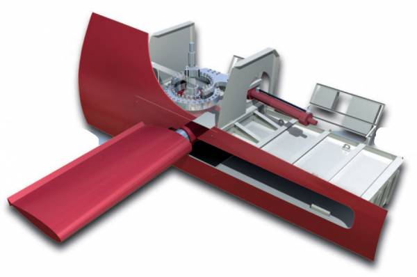
– Non-retractable fins are commonly used where space within the hull is limited. They are usually fitted at the turn of the bilge and do not project beyond the vertical line from the ship’s side or below the horizontal line of the ship’s bottom, to minimize the risk of contact with a quay wall or the dock bottom.
– The fin shaft, to which the fin is rigidly attached, passes through a sea gland in a mounting plate welded or bolted to the hull and is supported by two substantial bearings, A double-ended lever keyed to the inner end of the fin shaft is actuated by hydraulic rams supplied from an electrically driven variable delivery pump.
How the fin movement is controlled?

Thicker Lines = Hydraulic Lines; Thinner Lines = Electrical Lines
SCP = SOLAS Control panel, BCP = Bridge Control Panel, L = Ship’s Log, RIP = Remote Indicator Panel, SA = Ship’s Automation, LUB = Lube Oil Tank, CCU = Central Control Unit, RSU = Roll sensor Unit, LCU = Local Control unit, HPU = Hydraulic Power Unit, FU = Fin Unit.
– Control of fin movement is automatic and is usually derived from gyroscopic sensing gear which, in its simplest form — velocity control – is based on one small, electrically driven gyroscope mounted horizontally with its axis athwartships.
– The angular velocity of roll of the ship causes the gyroscope to process against centralizing springs to an amount proportional to the velocity and it generates a small force which is hydraulically amplified by a hydraulic relay unit to provide power sufficient to operate the controls of the variable delivery pump via suitable linkage.
– Part of the linkage is coupled to the fin shaft to transmit a cancelling signal to the pump control and to bring the fin to rest at the angle of tilt demanded by the sensing unit.
– This type of control is often fitted in small installations, usually for economic reasons, and is most effective against resonant rolling.
– Ships seldom roll in a purely resonant mode; the sea state is often highly confused. More elaborate, and more expensive, control systems are required to deal with suddenly applied roll, rolling at periods off resonance and rolling in conditions arising from the combination of several wave frequencies.
– A sensing unit based on a vertical-keeping gyroscope and a velocity gyroscope coupled into differentiating and summation units enables fin movement to be controlled by a composite function derived from roll angle, roll velocity and roll acceleration. By adding a ‘natural list’ unit, stabilization is achieved about the mean point of roll and so reduces both propulsion and stabilizing power demand. This is known as a compensated control system and is generally used in large installations.
RSU – Roll Sensor Unit in Detail (Compensated control system)
 – Roll reduction in excess of 90%, typically 30° out-to-out reduced to less than 3° out-to-out, can be achieved at resonance and low residual rolls can be maintained over a wide range of frequencies. However, since the stabilizing power varies as the square of the ship’s speed, fins are least effective at low or zero speed where they function only as additional bilge keels.