Load Line Regulations – A comprehensive guide
Load Line Regulations
INTRODUCTION
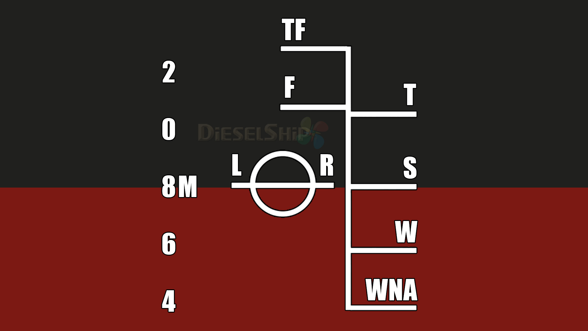
The Load line regulations have a long history of over 140 years. They were introduced in the British parliament by Lord Plimsoll, in the year 1854 and finally passed in 1876 as the first merchant shipping Act. As per this Act all Merchant ships were required to have a Load line marked on the ship side at the mid-ship length. This Load line mark has a circle with a diametrical line cut across the circle . This mark is also known as plimsoll mark and ships were allowed to load only till this line reached the waterline, thus preventing overloading of the ship. The rule adopted to determine this line was by referring to a table of Freeboards against length of ship and from it determine the allowable Freeboard. This Rule is still in force even in India for assigning Load line to sailing vessels.
With the advent of steel ships and powered propulsion, the very simple Load line regulations has slowly developed into a more elaborate set of rules covering all known aspects of flooding and damage control. The 1930 Load line regulations came into force after the development of steel ships powered by steam or I.C. engines . At That time tankers were also in vogue . The rules therefore catered to dry cargo ships as well as tankers and the concept of two separate tables of Freeboards based on length of ship was in existence then as it is now. Most of the rules now in force were also in force then.
The 1966 Load Line Convention happens to be the first International Load Line Convention after IMO (IMCO) came into existence. The Convention was held from third March to fifth April 1966 . The L/L Regulations being the outcome of this Convention was adopted on fifth April 1966. The Regulations came into force six months after it was officially adopted ie on fifth October 1966.
The special provisions in these regulations is the official recognition given to steel hatch covers and an incentive to adopt steel hatch covers instead of wooden hatch covers. By favouring ships with steel hatch covers by a reduction in summer Freeboard., thereby increasing their dead weight capacity . Hence in these regulations there are actually three sets of basing summer Freeboards. Table A for liquid bulk carriers (tankers) , Table B for dry cargo carriers with steel hatch covers and a third Table showing the increase in Freeboard from Table B for ships fitted with wooden Hatch covers.
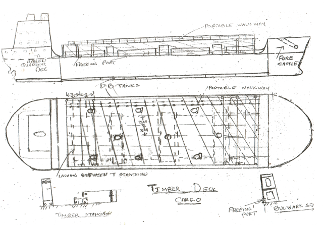
Another important feature in these regulations is the assignment of timber Load line to ships specially equipped to carry timber as deck cargo..Considering that timber is a buoyant cargo special regulations have been provided for carriage of timber deck cargo and conditions for its assignment. These are stated in chapter 4 of the Regulations.
The various chapters of these Regulations and their contents are shown in the following table:
| CHAPTER | HEADING | REGULATION NUMBERS |
| 1 | GENERAL | from 1 to 9 |
| 2 | CONDITIONS OF ASSIGNMENT | from 10 to 26 |
| 3 | FREEBOARDS | from 27 to 40 |
| 4 | SPECIAL REQUIREMENTS FOR SHIPS ASSIGNED TIMBER FREEBOARDS | from 41 to 45 |
| ANNEX 2 | Zones, Areas and Seasonal periods | |
| ANNEX 3 | CERTIFICATES |
OBJECTIVES OF ASSIGNING A LOAD LINE WITH FREEBOARDS
The goal objectives for assigning a load line to ships are twofold :
- To provide adequate reserve buoyancy against accidental flooding of any water-tight compartment in the
- To give protection to the crew on board for their safe movement within the
These goal objectives are realised by the following functional objectives, which are:
- Weather tight integrity of the freeboard or main deck
- Providing sufficient subdivision within the hull so that reserve buoyancy is sufficiently
- To provide adequate strength to the
- To provide comfortable and safe accommodation for the crew and facilities for their safe movement within the ship and to land ashore during port stay.
DIFFERENT FREEBOARD TABLES
The regulations provide primarily two separate tables, one for dry cargo vessels and another for liquid cargo vessels. From the tables one can observe that the basic freeboard for a tanker is considerably less than the freeboard of a dry cargo vessel of same dimensions. The reasons are as follows:
- Weather-tight integrity of freeboard deck : – The tanker has small openings for cargo ullaging and tank entry on the freeboard deck, which can be efficiently maintained in tight condition as compared to the dry cargo carrier which has large hatch covers for the holds which are rather difficult to maintain in a weather tight
- Cargo space subdivision :- Considering two equally dimensioned ships , one a tanker and the other a dry cargo vessel, the tanker has its cargo space divided into 3*5=15 tanks by transverse and longitudinal bulkheads, whereas the dry cargo vessel’s cargo space is divided into 5 holds by transverse bulkheads. The reserve buoyancy potential for the tanker becomes superior to the dry cargo vessel’s reserve
- Hull strength :- The tanker hull strength is superior to the dry cargo ship strength of same The longitudinal bulkheads and Isherwood framing system improve considerably the resistance to overcome large bending moments the tanker is subjected to. The large web frames within the tanker assist the tanker to resist the large shear forces the tanker is subjected to. This aspect makes the tanker more stronger than the dry cargo ship of equal dimensions.
- Permeability ;- In a tanker because of the liquid nature of the cargo which fills up the cargo space to its full level, the permeability of sea water entering the cargo space due to bilging is very negligible as compared to a dry cargo vessel whose permeability of the cargo space is about 60% on an average
Taking into account all the above factors all of which are in favour of the tanker, the regulations provide for a considerable difference in the freeboards of these vessels.
SUMMARY OF THE REGULATIONS
1Strength of hullShips built and maintained in accordance with class regulations are considered to have adequate strength.10Information to be supplied to the masterThe need to provide a ship specific approved stability booklet with relevant damage stability calculations for masters use. Where D is less than L/15 no reduction in freeboard.
| Chapter | Reg no. | Title | Objective and brief summary |
Chapter 1 – General |
1 | Strength of hull | Ships built and maintained in accordance with class regulations are considered to have adequate strength. |
| 2 | Application | Applies to all sea going ships , except naval ships. | |
| 3 | Definition of terms used in the | Appropriate meaning of technical words used with reference to these regulations meanings of some important terms (*1) | |
| 4 | Deck line | Freeboard deck ref line, 300mm long and 25mm thick painted on the midship side edge. | |
| 5 | Load line mark | Also known as the plimsoll mark, a circle 25 mm thick intersected by a diametrical line 25 mm thick | |
| 6 | Lines to be used with the load line mark | The various freeboard lines used with loadline mark each 25mm thick. | |
| 7 | Mark of assigning authority | Authority to the classification society which has classed the ship to put its initials on the load line mark. | |
| 8 | Details of marking | Explains the colour contrast and method of marking | |
| 9 | Verification of marks | Function of the class to verify the relevant freeboards and confirm it is in accordance to the certificate. | |
Chapter 2 – Conditions of assignment |
10 | Information to be supplied to the master | The need to provide a ship specific approved stability booklet with relevant damage stability calculations for masters use. |
| 11 | Superstructure end bulkheads | Shall be of efficient construction and if needed fitted with approved steel weather tight doors. | |
| 12 | Doors | Specification of approved type steel weather tight doors fitted on all access openings on exposed decks | |
| 13 | Position of hatchways, doorways and ventilators | Weather-tight integrity. | |
| 14 | Cargo and other hatchways | Weather-tight integrity. | |
| 15 | Hatchways closed by portable covers and secured weather-tight by tarpaulins and battening devices. | Specification of older type wooden hatch covers with steel hatch beams. | |
| 16 | Hatchways closed by weather tight covers of steel or other equivalent material fitted with gaskets and clamping devices | Specification of steel hatch covers with securing devices. | |
| 17 | Machinery space openings | Weather tight access to machinery spaces .Weather tightness of skylights and fiddley deck. | |
| 18 | Miscellaneous openings in freeboard and superstructure decks | Weather-tight integrity . | |
| 19 | Ventilators | Weather-tight specifications for cargo hold ventilators. | |
| 20 | Air pipes | Specifications for construction and efficient means of prevention of ingress of seawater into tanks to which these air pipes are connected. | |
| 21 | Cargo ports and other similar openings | specifications for water tight fittings and securing devices particularly when the openings are below the freeboard deck. | |
| 22 | Scuppers, inlets and discharges | Efficient leak proof connections to ship side using doubler flange fitting. water tight integrity | |
| 23 | Side scuttles(port holes) | Specifications of approved type portholes with deadlight blanks. Weather-tight integrity for side scuttles fitted above freeboard deck and water tight integrity for side scuttles fitted below freeboard deck. | |
| 24 | Freeing ports | Prevention of accumulation of sea water on freeboard deck, especially in ships fitted with bulwarks. | |
| 25 | Protection of the crew | Safe weather proof quarters for the accommodation of crew and provision for their safe movement within the ship and for entering as well as leaving the ship. | |
| 26 | Special conditions of assignment for type ‘A’ Ships | Weather-tight fittings for access to pump room, provision of catwalk connecting accommodation house to forecastle and freeing ports if bulwarks are fitted | |
Chapter 3 – Freeboards |
27 | Types of ships | Lists tankers(A-type) and dry cargo ships fitted with approved type steel hatch covers(B-type) and(*2) conditional specifications for B-60 and B-100 (B-type) ships. Table for increase of freeboard for ships fitted with wooden hatch covers. |
| 28 | Freeboard tables | Table A for tankers , Table B for Dry cargo ships fitted with steel hatch covers. | |
| 29 | Correction to the freeboard for ships under 100m in length. | Increase in freeboard by defined formula. | |
| 30 | Correction for block coefficient | Standard Cb = 0.68 .Freeboard correction factor=(Cb+0.68)/1.36 | |
| 31 | Correction for depth | Standard L/D =15, where D is greater than L/15 the freeboard is increased by( D-L/15)*L/0.48 mm, at lengths less than 120 metres and 250 mm at 120 metres length and above. Where D is less than L/15 no reduction in freeboard. | |
| 32 | Correction for position of deck line | Applies to ships with rounded gunwale. The position of deck line is shifted below at the junction of sheer strake. No change in freeboard. | |
| 33 | Standard height of superstructure | Standard height varies from 1.8 to 2.3 m as per length of superstructure. | |
| 34 | Length of superstructure | Length of superstructure with attachments within the length of the ship | |
| 35 | Effective length of superstructure | Net length of superstructure. | |
| 36 | Trunks | Trunks are similar to deck houses which do not extend to the sides of the ship. Examples are deck houses on bulkcarriers on which the cargo cranes are mounted. They are fitted with weather tight closing doors and fittings. | |
| 37 | Deduction for superstructure and trunks | Proportional reduction in freeboard as per length of superstructure and trunks. | |
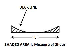
| 38 | Sheer | Sheer is the upward curvature of the Freeboard deck line. The measure of sheer will be explained later as a separate explanation (*2) | |
| 39 | Minimum bow height | Separate explanation (*4) | |
| 40 | Minimum Freeboards. | Summer Freeboard:- obtained after all above corrections applied to tabular Freeboard.
Tropical Freeboard:- Summer Freeboard – d/48 m Winter Freeboard:-Summer Freeboard + d/48 m Summer Fresh :- Summer Freeboard + ?/40T Tropical Fresh:-Tropical Fresh +?/40 Winter N A:- For ships less than 100 m long :- Winter Freeboard +50mm. Where ? is the displacement at summer draft, T IS T.P.C. at summer draft, and d is summer draft. |
|
Chapter 4 – Timber Freeboards |
41 | Application of this chapter | Regulations 42 to 45 are in this chapter. |
| 42 | Definitions | 1Timber deck cargo :- The term ‘ ‘timber deck cargo’ means a cargo of timber carried on an uncovered part of the freeboard deck or the superstructure deck. The term does not include wood pulp or similar cargo ( ply wood )
(2)Timber load line:- A timber deck cargo may be regarded as giving a ship a certain additional buoyancy and a greater degree of protection against the sea.. For that reason ships carrying a timber deck cargo may be granted a reduction of freeboard calculated according to the provisions of regulation43,44 and 45 and marked on the ship side as separate Timber freeboards. |
|
| 43 | Construction of ship | Superstructure:- Ships shall have a forecastle of at least standard height and a length of .07 L. and a raised quarter deck with either a deck house or a strong steel hood of at least same bow height
D.B . tanks :-DB tanks where fitted within the mid-ship half length of the ship shall have adequate water-tight longitudinal subdivision. Bulwarks:- The ship will be fitted either permanent bulwarks at least 1 metre in height, specially stiffened on the upper edge and supported by strong bulwark stays attached to the deck and provided with necessary freeing ports. ,or with efficient rails of the same height and of specially strong construction. |
|
| 44 | Stowage | Detailed specifications given for proper stowage, timber uprights and lashings.
Stability:-Stability working should include water retention constant on deck for calculating transverse GM and Trim and the range of stability should be drawn for Arrival and Departure conditions Protection of crew :- A portable catwalk at least 30 cms wide to be constructed on top of the stowed timber for the crew to proceed to the forecastle as well as to check the lashings on a daily basis during the loaded passage. Two rope ladders one forward and one aft to be fitted to access the catwalk. |
|
| 45 | Computation of Freeboard | The minimum summer freeboard is worked out by applying regs27,28,29,30,31,32,37 and 38. The principle used is that the entire length of the stowed timber deck cargo is considered as a virtual superstructure and the allowable reduction in freeboard as per reg37 specially modified and given in this regulation as based on length of superstructure.
Referring to position of summer freeboard the other freeboards are placed as follows:- Winter Freeboard :- Summer freeboard + d/36 m Tropical Timber Freeboard:- Summer Freeboard –d/48 m Fresh water timber freeboard shall be in accordance to reg 40 WNA timber freeboard shall be in accordance to reg 40 |
Explanations
-
Definitions
- Superstructure:- A superstructure is a decked structure on the freeboard deck extending from side to side of the ship or with the side plating not being inboard of the shell plating more than 4 percent of the breadth (B). A raised quarter deck is regarded as a superstructure.
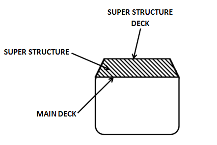 In common parlance superstructure means any construction above the main deck.. This however is not correct and what is stated above is the correct meaning of superstructure with reference to ship construction.
 - Water- tight :- Means prevention of leakage of water from a closed opening when the closure is subjected to a predetermined head of water. Example—water-tight door in engine room which is subjected to a head of sea water up to main deck level.
- Weather-tight:- Means prevention of leakage of water from a closed opening when the closure is subjected to a strong spray of water, such as a swell hitting a weather tight door. Water –tight condition is more stronger than Weather tight condition.
- Superstructure:- A superstructure is a decked structure on the freeboard deck extending from side to side of the ship or with the side plating not being inboard of the shell plating more than 4 percent of the breadth (B). A raised quarter deck is regarded as a superstructure.
-
B-60 and B-100 SHIPS
B-60 :- Dry cargo ships of over 100 metres in length, when loaded up to summer draught, will remain afloat in a satisfactory condition of equilibrium after flooding of any single damaged compartment at an assumed permeability of 0,95 excluding the machinery space. In such ships the freeboards shall be reduced to not more than 60% of the difference between table A and table B for the same length of ship.
B-100:- In dry cargo ships of over 225 metres in length, the machinery space will be treated as a floodable compartment with an assumed permeability of 0,85. The ship will remain afloat in a satisfactory condition of equilibrium after flooding of any single damaged compartment with assumed permeability 0,95 and the machinery space with assumed permeability of 0.85.In such ships the freeboards shall be reduced to not more than 100% of the difference between table A and table B for the same length of the ship.Limits of status and stability in damaged condition:- The following limits may be regarded as satisfactory:
- The final water line after flooding is below the lower edge of any opening through which progressive flooding may take place
- The maximum angle of heel due to unsymmetrical flooding is of the order of 15 degrees.
- The metacentric height in the flooded condition is
-
Calculation of deck sheer
The deck sheer, which is the upward curvature of the deck plating starting from mid-ship to the ends forward and aft is provided to restrict the water entering the deck when the ship pitches in a heavy sea. The standard sheer profile is specified under regulation 38. Standard sheer profile stipulates that the forward sheer is twice the aft sheer and this is provided to prevent shipping water on deck as the ship moves forward in a rough sea.
 The standard sheer profile for after half and forward half of the Freeboard deck is given in two tables as under: L is length of ship.
After Half
Station Ordinate (in mm) Factor After perpendicular 25(L/3 +10) 1 1/6 L from AP 11.1(L/3+10) 3 1/3L from AP 2.5 (L/3 +10) 3 Amidships 0 1 Forward Half
Station Ordinate (in mm) Factor Amidships 0 1 1/3L from FP 5.6 (L/3 +10) 3 1/6 L from FP 22.2(L/3 +10) 3 Forward perpendicular 50(L/3 +10) 1 The profile area of the two halves in terms of length is given as follows ; Forward half = 44’47 L +1334 mm2.
Aft half = 22.23 L + 667 mm2
Consider a ship of length 200 metres. As per above calculation the standard forward half sheer area will be = 44.47*200 +1334 =9561 mm2
The Aft half standard sheer area will be = 22.23 *200 + 667 =5113mm2.
Reg 38.9 states as follows “Where the sheer profile differs from the standard, the four ordinates of each profile in the forward or after half shall be multiplied by the appropriate factors given in the table of ordinates. The difference between the sums of the respective products and those of the standard divided by 8 measures the deficiency or excess of sheer in the forward or after half. The arithmetical mean of the excess or deficiency in the forward and after halves measures the excess or deficiency of sheer
Forward Half
Station Ordinate (in mm) Factor Amidships 0 1 1/3 L from FP 200 3 1/6 L from FP 400 3 Forward perpendicular 600 1 After Half
Station Ordinate (in mm) Factor Amidships 0 1 1/3L from AP 100 3 1/6L from AP 200 3 After perpendicular 300 1 Forward sheer area = 2400mm2 , After sheer area =1200mm2
Applying reg 38.9 we have:
Deficiency Forward sheer = [latex]frac{9561-2400}{8} = frac{7161}{8} =895.125 mm[/latex]
Deficiency after sheer = [latex]frac{5113-1200}{8} = frac{3913}{8} = 489.125 mm[/latex]
The average deficiency =[latex]frac{(895.125+489.125)}{2}= 692.125 mm[/latex]
Therefore 692.125 mm will be added to the tabular freeboard
Reg 38.14 : Addition for deficiency in sheer :- Where the sheer is less than the standard, the correction for deficiency in sheer shall be added to the Freeboard.
Reg 38.12 Where sheer credit is given for a poop or forecastle, the following formula shall be used;
S=y/3* L’/L
Where s=sheer credit to be deducted from the deficiency or added to the excess of sheer
Y=difference between actual and standard height of superstructure at the end of sheer.
L’= mean enclosed length of poop or forecastle up to a maximum length of
0.5L and L=length of ship (LBP)
-
Minimum Bow height
The bow height is defined as the vertical distance at the forward perpendicular between the waterline corresponding to the assigned summer freeboard and the designed trim and the top of the exposed deck at side shall not be less than;
For ships below 250 metres in length,[latex]frac{56 ast L (frac{1-L}{500})ast 1.36}{C_b + 0.68}[/latex] millimetres.
For ships of 250metres and above in length,
[latex]frac{7000times 1.36}{C_b + 0.68}[/latex] millimetres.
Where L is the length of the ship in metres and CB is the block coefficient which is to be taken not less than 0.68