INSPECTION AFTER DOCKING THE SHIP IN DRYDOCK

INSPECTION AFTER DOCKING THE SHIP IN DRYDOCK
SCOPE OF DRY-DOCKING, INSPECTION AND REPAIR TO BE CARRIED OUT
(1)BOTTOM INSPECTION AND CORRECTIVE ACTION AS RECOMMENDED BY CLASSIFICATION SOCIETY SURVEYOR.
SCOPE OF DRY-DOCKING, INSPECTION AND REPAIR TO BE CARRIED OUT.
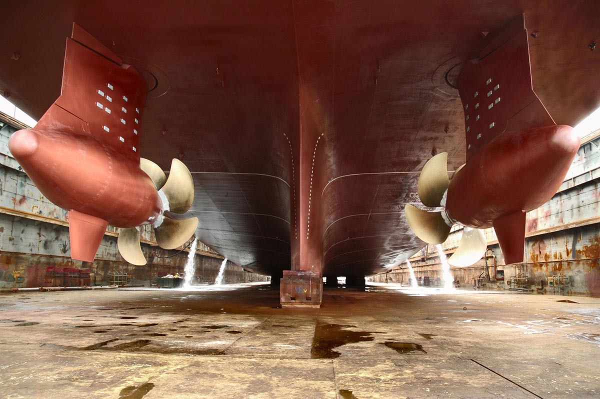
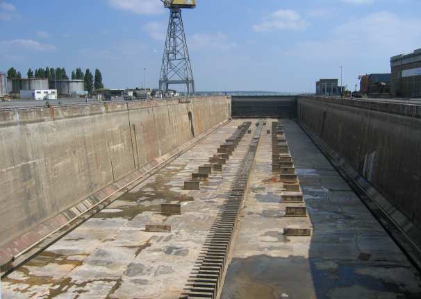
- This is the first visit of the surveyor on the ship. This inspection is carried out as soon as the water is pumped out and the dock is dry, with the ships bottom scraped free of barnacle growth. This inspection is usually carried out during daylight hours especially after daybreak.
- In case the ship docks late in the night the inspection will be carried out on the following morning. The attending superintendent along with Master ,C/E, C/O, and 2/E will enter the dock and go around the ship from forward to aft. Duration of this inspection is about one hour. The yard attending repair manager will also be present during this inspection.
- This is a general inspection and any noticeable defects will be further examined and corrective action taken accordingly. Normally the defects noticed are of two types:
(a) Dents which are deep and spread over a small area are further examined internally to note the extent of damages to stiffeners fitted internally so that the damaged portion of the stiffeners /stiffener are renewed along with the dented shell plating.
(b) Areas of shell plating which have eroded and wasted badly are tobe U.S . gauged and if needed renewed to the extent required.
(2)BOTTOM PREPARATION AND PAINTING AS PER COMPANY‘S PAINTING SPECIFICATIONS.
- This is the first objective in dry docking , commences on the first day and continues till almost to the last day in dry dock. On the first day the areas requiring grit blasting are decided by the superintendent in consultation with the paint suppliers technical officer and the yard’s painting department manager.
- The areas where heavy grit blasting are required on an average are as follows :
(a) Top sides about 40% of the total top side area. After grit blasting two coats of primer paint put each coat 30 microns.
(b) The Boot top about 60% of the total belt area consisting of the wind and weather strakes extending from summer load line to L.W.L . After grit blasting to apply two coats of primer paint each coat 40 microns. thick.
(c) On the bottom side the grit blasting area is negligible and at the most does not exceed about 5%. Two coats of primer paint must be applied on the blasted areas.
(d) The full painting specification now as an example is as follows
Top side:- Two coats primer paint each coat 40 microns thick and two coats finish paint, 40 microns thick, each coat.
Boot Top:- Two coats primer paint each coat 40 microns thick, two coats finish paint ,each coat 40 microns thick. Anti fouling paint one coat 40 microns thick.
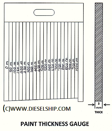
Bottom:- Two coats primer paint 40 microns thick each coat. Two coats finish paint 40 microns thick each coat. One coat anti fouling paint 40 microns thick. - During the painting process the paint suppliers’ technical officer checks the coating thickness using a paint thickness gauge which is a strip of plating about 3 mm thick with markings which whilst scrapping the half dried paint indicates the thickness by the thickness noted on the plate gauge.(Refer to Fig below). The paint is applied by airless spray nozzles. The Technical officer also inspects the blasted strakes before the primer paint is applied.

Paint thickness gauge
(3) ANCHOR CABLES RANGING AND CALIBRATION.
- Both the anchors along with their cables are lowered into the dock bottom and the chains are ranged to enable the chains to be calibrated.
- The diameters of the links are checked and noted and shown to the surveyor.
- Links on any chain length which have wasted are discarded by renewing the chain length utilizing the spare chain length.
- The ship always carries one spare length as per regulations. This length is attached to either the port or starboard anchors.
- It is a good practice to turn the chains end to end at each dry docking so that the link wear is uniform.
(4) CLEANING AND PAINTING OF CHAIN LOCKER.
- The chain wells are cleaned of mud and accumulated water and painted with a slow drying chlorinated rubber based paint. This work can only be done in dry dock since the anchors and chains are taken out into the dry dock.
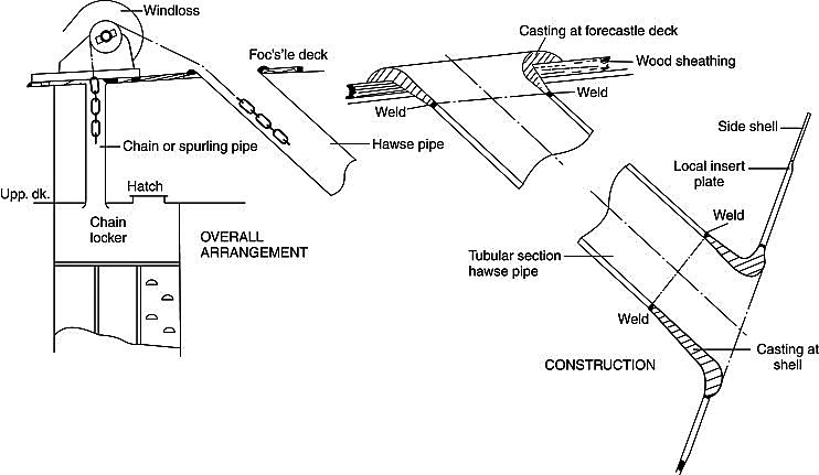
(5) BUILDING UP THE HAWSE PIPE CAST STEEL COLLARS AT BOTH ENDS.
- Due to the frequent rubbing of the chain links on the collars during anchor dropping and heaving up the anchors, the collars get heavily grooved and if neglected can cause damage to the hawse pipes. Hence this work is done during dry docking when the hawse pipes are free of the chains.(Refer to Fig below).
(4) ECHO-SOUNDER TRANSDUCERS CLEANING AND CHECKING OF WATER TIGHT TERMINAL BOXES
- The echo sounders are serviced and the cables are checked for continuity and earth after cleaning the connections in the terminal box. The transducer plates are cleaned and a coat of fish oil applied on the transducers.
(5) SPEED LOG / SAL LOG OR DOPPLER SPEED LOG
- The ship may be fitted with a Doppler speed log or a Sal log in the case of older ships. These equipments are to be serviced and calibrated.
- The dry dock provides the best situation for verification since any transducers fitted underwater can be thoroughly checked and renewed if they are faulty.
(6) SACRIFICIAL ZINC ANODES OR IMPRESSED CURRENT SYSTEM
- All zinc sacrificial anodes are to be renewed. Most of them would be completely wasted, if any un-wasted anodes are found they are not of good quality and hence must be renewed.
- The number of zinc anodes should not be reduced as they are calculated as a total quantity of zinc to be distributed all over the hull surface especially on the bilge keels, the stern portion and on the rudder.
- The total mass of zinc used is proportional to wetted surface area of the ship and the mass of the propeller.
- If the ship is fitted with an impressed current system then it must be serviced and calibrated.
(7) SEA CHESTS CLEANING AND PAINTING.
- All ships are fitted with at least 2-3 sea chests in the machinery space area. They are high sea suction , the low sea suction and the emergency fire pump sea suction.
- Their suction grids are to be dismantled and cleaned.
- The internal surface of the chests have to be scraped clean of all growth.
- In case of doubt the casing plate thicknesses have to be gauged for thickness and renewed as necessary.
- After cleaning they are to be painted in accordance to the ships hull painting specification.
- Zinc anodes in the sea chests are to be renewed.
(8) SEA SUCTION AND DISCHARGE VALVES OVERHAUL AND SURVEY.
- All sea suction and discharge valves are to be overhauled at every dry docking. Every alternate dry docking they are surveyed.
- The air and/or steam connections to the suction boxes must be checked and any defects also attended.
- Many shipping companies also overhaul the main intermediate valves and attached mud filters.
(9) SANITARY STORM VALVES OVERHAUL AND THEIR SURVEY.
- All storm valves flaps will be dismantled, their leather washers renewed and defective hinge pins renewed.
- The soil pipes will be inspected for any signs of excessive corrosion, cracks and necessary renewals carried out.
- The provision of storm valves is a mandatory requirement under L.L Regulations even if the ship is fitted with a sewage treatment plant.
(10) DAMAGED PORTIONS OF BILGE KEELS TO BE RENEWED.
Any portion of the bilge keels which are found damaged will be suitably renewed.
(11) RUDDER PINTLE CLEARANCES, JUMPING CLEARANCE, ANY REPAIRS AND HYDRAULIC TESTING
- The rudder bottom plug is opened out in dry dock. If accumulated water comes out, it indicates the rudder plating is cracked and hence sea water has found its way into the rudder making it heavy causing the rudder movement sluggish. Hence the location of the damage has to be found out and then suitably repaired.
- For this the rudder top plug is opened, The bottom plug refitted and rudder filled up with water through top plug. The location of the damage will be found out by water seen leaking out from the hole/crack. Suitable repairs can now be carried out and finally an hydrostatic test can be carried out by filling water into the rudder through a flexible rubber tube fitted at the top plug and a funnel at the end of the rubber pipe , with the funnel held at the summer load line level.
- This test proves the tightness of the repair when the rudder internally is subjected to head of water up to summer load line. The internal surface of the rudder is now painted by a process of paint displacing the water, whereby the paint resting on the water surface spreads all around internally whilst the water level is being lowered through the bottom plug.
- This method is called float coat method using a rubber based paint of lower density and slower drying rate. All paint manufacturers supplying ship’s paints make this kind of paint.
- The pintle bush clearance for top and bottom pintles are to be measured using long feeler gauges.The allowable pintle bush clearance is 1.5 mm for pintle dia up to 200 mm. For dia exceeding 200 mm the clearance is proportionately increased.
- If the clearances are excessive the bushes are to be renewed after dismantling the rudder. The clearances are taken at port , starboard, forward and aft and the maximum of these is the clearance.
- The rudder drop is measured using the rudder trammel gauge , but many ships are not not checking the rudder drop since the verification of jumping clearance gives the same information.
- The verification of jumping clearance is carried out by comparing the clearance at the jumping bar under the rudder skeg with the clearance at the steering gear X- head .
- The clearance at the X-head should be more than the jumping clearance to prevent the X- head interfering with the Rams and damaging the Rams. Jumping clearance can increase by wear of the rudder pedestal bearings or by the jumping bar falling off the rudder if the welding holding the bar has given way . If the pedestal bearing has worn off the rudder is to be jacked up and the pedestal bearing halves dismantled, the bearings built up by welding and suitably machined.


